


MEMORY INTERFACING
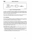
(FROM
82380)
V"
1--___
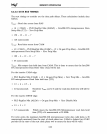
RFRQ
TOUTI/REF# ----t"" )
HLOA
Piji.----....;..--L-~
. (TO ORAMP1 PLD)
(FROM
i386'"
OX CPU)
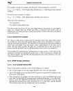
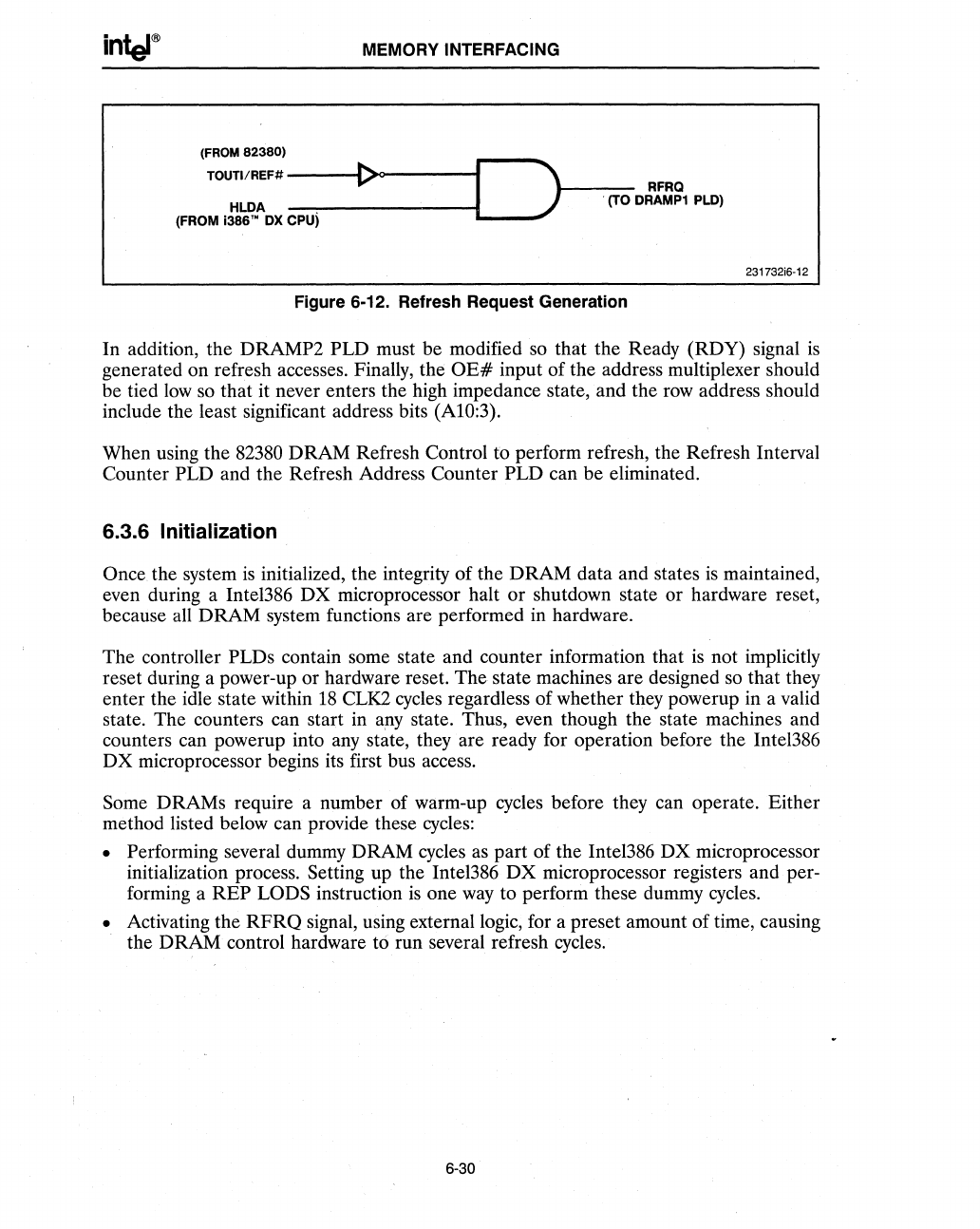
Figure 6-12. Refresh Request Generation
231732i6-12
In addition, the DRAMP2 PLD must be modified so that the Ready (RDY) signal
is
generated on refresh accesses. Finally, the
OE#
input of the address multiplexer should
be tied
low
so
that it never enters the high impedance state, and the
row
address should
include the least significant address bits (AlO:3).
When using the
82380
DRAM Refresh Control to perform refresh, the Refresh Interval
Counter
PLD and the Refresh Address Counter PLD can be eliminated.
6.3.6 Initialization
Once the system
is
initialized, the integrity of the DRAM data and states
is
maintained,
even during a Intel386 DX microprocessor halt or shutdown state or hardware reset,
because all DRAM system functions are performed in hardware.
The controller PLDs contain some state and counter information that
is
not implicitly
reset during a power-up or hardware reset. The state machines are designed so that they
enter the idle state within
18
cue
cycles regardless of whether they powerup in a valid
state. The counters can start in
apy state. Thus, even though the state machines and
counters can powerup into
any
state, they are ready for operation before the Inte1386
DX microprocessor begins its first bus access.
Some DRAMs require a number of warm-up cycles before they can operate. Either
method listed below can provide these
cycles:
• Performing several dummy DRAM cycles
as
part of the Intel386
DX
microprocessor
initialization process. Setting up the Intel386 DX microprocessor registers and
per-
forming a
REP
LaDS
instruction
is
one
way
to perform these dummy cycles.
• Activating the
RFRQ
signal, using external logic, for a preset amount of time, causing
the DRAM control hardware
t6 run several refresh cycles.
6-30