PHYSICAL DESIGN AND DEBUGGING
Mter
installing the EPROMs, the
READY#
line should be tied high (negated) so that
the Inte1386
DX
microprocessor begins its first bus cycle after reset and then continues
to add wait states. While the system
is
in this state, the circuit should be probed to verify
signal states, using a voltmeter
or
oscilloscope probe.
The programmer should check whether the address latches have latched the first address
and whether the address decoder
is
applying a chip-select signal to the EPROMs. The
EPROMs should be emitting the first four opcode bytes of the first code to be executed
(90H, 90H, EBH, FCH for the 4-byte program of Figure 11-28), and the opcode should
be propagating through the data transceivers to
the.
Intel386
DX
microprocessor data
pins.
Then the READY # input should be connected to the READY # generation logic, the
Intel386
DX
microprocessor, and the results should be tested when the simple program
runs. Because the program loops back on itself, it runs continuously.
At
this point, the
system has progressed to running multiple bus cycles,
so
a logic analyzer
is
needed to
observe the dynamic behavior of the system.
When the
EPROMs programmed with the simple 4-byte diagnostic program are
..
installed and the Inte1386
DX
microprocessor
is
executing the code, the LED indicator
for
ADS#
(if included in the system)
glows,
because
ADS#
is
generated for each bus
cycle
by
the Inte1386
DX
microprocessor.
It
is
necessary to check that the EPROMs are
selected for each code fetch cycle. After system operation
is
verified with
the
simple
program, more complex programs can be run.
11.8.5 Other Simple Diagnostic Software
Other simple programs can be used to check the other operations the system must
perform. The program described here
is
longer than the 4-byte program illustrated pre-
viously; it tests the abilities to write data into RAM and read the data back to the
Inte1386
DX
microprocessor.
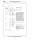
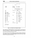
This second diagnostic program, shown in Figure 11-29,
is
also suitable for placing into
EPROMS. Because this diagnostic loops back to itself, the
ADS#
LED should glow
continuously, just
as
it does when running the 4-byte program.
The program in Figure
11-29
is
based on the assumption that hardware exists to report
whether the data being read back from RAM
is
correct. This hardware consists
of
a
writable output latch that can display a byte value written to it. The byte value written
is
a function of the RAM data comparison test.
If
the data
is
correct, the byte value written
is
AAH (10101010); if the data
is
incorrect, 55H (01010101)
is
written.
This diagnostic program
is
not comprehensive, but it does exercise EPROM, RAM, and
an output latch to verify that the basic hardware works.
The program
is
short
(45
bytes) to be easily understood. Because it
is
short and because
it loops continuously, a logic analyzer or even an oscilloscope can
be
used to observe
system activity.
11-37


