LOCAL
BUS
INTERFACE
the bus before the end of the current bus cycle. Therefore, because both signals are
sampled at the same sampling window,
BSI6#
must be active before or at the same time
as
NA#
to guarantee 16-bit operation. Once
NA#
is
sampled active in a bus cycle and
BSI6#
is
not active at that time,
BSI6#
must be negated for the remainder of the bus
cycle.
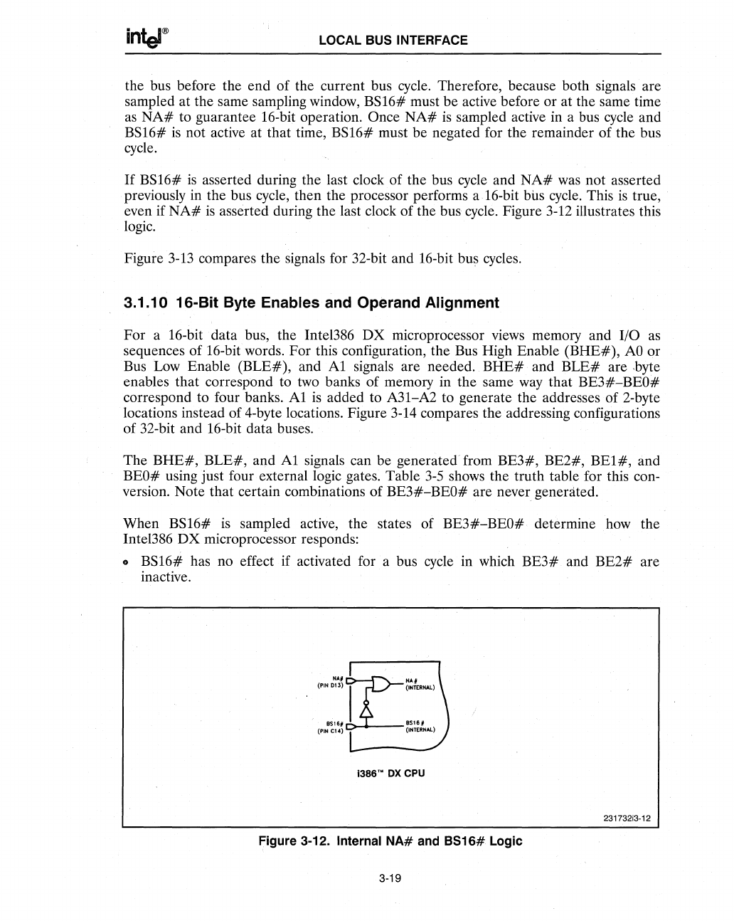
If
BSI6#
is
asserted during the last clock of the bus cycle and
NA#
was not asserted
previously in the bus cycle, then the processor performs a 16-bit
bus cycle. This
is
true,
even if
NA#
is
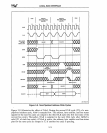
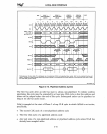
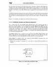
asserted during the last clock of the bus cycle. Figure 3-12 illustrates this
logic.
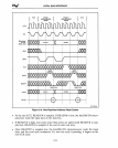
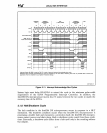
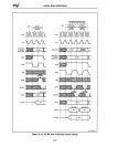
Figure 3-13 compares the signals for 32-bit and 16-bit bus cycles.
3.1.10
i6-Bit
Byte Enables and Operand Alignment
For
a 16-bit· data bus, the Intel386
DX
microprocessor views memory and I/O
as
sequences of 16-bit words.
For
this configuration, the Bus High Enable
(BHE#),
AO
or
Bus Low Enable
(BLE#),
and
Al
signals are needed.
BHE#
and
BLE#
are ,byte
enables that correspond to two banks of memory in the same way that
BE3#-BEO#
correspond to four banks.
Al
is
added to A31-A2 to generate the addresses of 2-byte
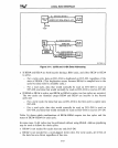
locations instead of 4-byte locations. Figure 3-14 compares the addressing configurations
of 32-bit and 16-bit data buses.
The
BHE#,
BLE#,
and
Al
signals can be generated from
BE3#,
BE2#,
BEl#,
and
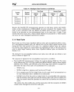
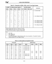
BEO# using just four external logic gates. Table
3-5
shows the truth table for this con-
version. Note that certain combinations
of
BE3#-BEO#
are never generated.
When
BSI6#
is
sampled active, the states of
BE3#-BEO#
determine how the
Intel386
DX
microprocessor responds:
..
BSI6#
has no effect if activated for a bus cycle in which
BE3#
and
BE2#
are
inactive.
NAIIL1NAI
(PIN
013)
I
(lNTtRNAL)
85161
BS1S,
(PIN
CI4)
T
('NTERNAL)
-
i38S'·
ox
CPu
231732i3-12
Figure 3-12. Internal
NA#
and
8S16#
Logic
3-19


