LOCAL
BUS
INTERFACE
BUS MASTER 1
READS
VALUE 0
= NOT BUSY
BUS MASTER
1
WRITES
VALUE
1 = BUSY
BUS
MASTER
1
HAS
CONTROL
OF
DEVICE
SEMAPHORE
-EJj
-8
NO
ERROR
SEMAPHORE
BUS
MASTER 1 r::1
READS
-~
VALUE
O=NOT
BUSY /
/
LOCKED
CYCLES
BUS MASTER
2
READS
VALUE
1 = BUSY
BUS MASTER
2
WAITS FOR
VALUE TO
CHANGE
UNLOCKED /
r;;1_
CYCLES \
L.:J
BUS MASTER 2
READS
VALUE 0
=
NOT
BUSY
\
\
BUS MASTER 1
EJ
WRITES - 1
VALUE 1 = BUSY
EJ--
BUS MASTER 2
WRITES
VALUE
1 = BUSY
ERROR
BOTH
BUS
MASTERS
TRY
TO
CONTROL
DEVICE
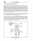
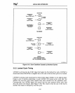
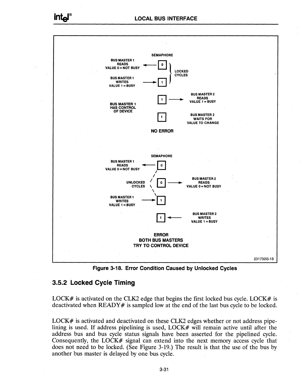
Figure 3-18. Error Condition Caused by Unlocked Cycles
3.5.2 Locked Cycle Timing
231732i3-18
LOCK#
is
activated on the CLK2 edge that begins the first locked bus
cycle.
LOCK#
is
deactivated when READY #
is
sampled
low
at the end of the last bus cycle to be locked.
LOCK#
is
activated and deactivated on these CLK2 edges whether or not address pipe-
lining
is
used.
If
address pipelining
is
used,
LOCK#
will remain active until after the
address bus and bus
cycle
status signals have been asserted for the pipe lined. cycle.
Consequently, the
LOCK# signal can extend into the next memory access cycle that
does not need to be locked. (See Figure 3-19.) The result
is that the use of the bus
by
another bus master
is
delayed
by
one bus
cycle.
3-31


