


MUL TIBUS I AND Intel386
DX
MICROPROCESSOR
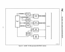
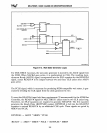
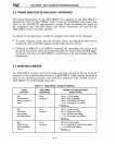
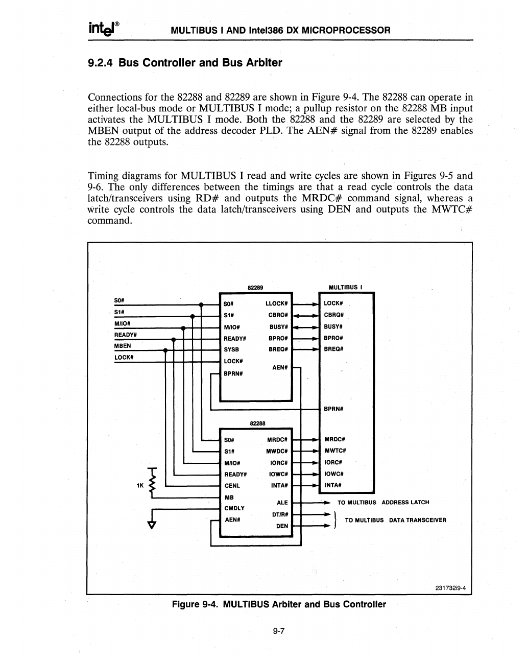
9.2.4 Bus Controller and Bus Arbiter
Connections for the
82288
and
82289
are shown in Figure
9-4.
The
82288
can operate in
either local-bus mode or
MULTIBUS I mode; a pullup resistor on the
82288
MB
input
activates the
MULTIBUS I mode. Both the
82288
and the
82289
are selected
by
the
MBEN output of the address decoder
PLD. The
AEN#
signal from the
82289
enables
the 82288 outputs.
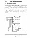
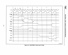
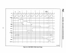
Timing diagrams for
MULTIBUS I read and write cycles are shown
in
Figures
9-5
and
9-6.
The only differences between the timings are
that
a read cycle controls the data
latch/transceivers using
RD#
and outputs the
MRDC#
command signal, whereas a
write cycle controls the data latch/transceivers using
DEN
and outputs the
MWTC#
command.
82289
MULTIBUS I
SO#
so#
LLOCK#
r----
LOCK#
SI#
SI#
CBRO#
I-
CBRa#
MIIO#
MIIO#
BUSY#
I--
BUSY#
READY#
READY#
BPRO#
r----
BPRO#
MBEN
SYSB
BREa#
r--
BREa#
LOCK#
LOCK#
AEN#
I-
r-
BPRN#
BPRN#
82288
---
SOt
MRDC#
...
+--
MRDC#
'---
SI#
MWDC#
t--f--
MWTC#
MIIO#
IORC#
H"-
IORC#
-
....
>
READY#
IOWC#
H--
IOWC#
lK
•
CENL
INTA#
r-f-
....
INTA#
MB
ALE
TO
MULTIBUS
ADDRESS
LATCH
CMDLY
*
DTIR#
}
I
AEN#
TO
MULllB
DEN
US
DATA TRANSCEIVER
231732i9-4
Figure 9
..
4.
MULTIBUS Arbiter and Bus Controller
9-7