


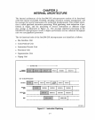

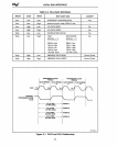
LOCAL BUS INTERFAcE
• The CLK2 input provides a double-frequency clock signal for synchronous operation.
This signal
is
divided
by
two
internally, so the Intel386
DX
microprocessor fundamen-
tal frequency
is
half the CLK2 signal frequency. For example, a 20-MHz Intel386
DX
microprocessor uses a
40-
MHz CLK2 signal.
• The RESET input forces the Intel386
DX
microprocessor to a known reset state.
• The HOLD signal can be generated
by
another bus master to request that the
Intel386
DX
microprocessor release control of the bus. The Intel386 DX micropro-
cessor responds
by
activating the Hold Acknowledge (HLDA) signal
as
it relinquishes
control
of
the local bus.
• The Maskable Interrupt (INTR) and Non-Maskable Interrupt (NMI) inputs cause
the Inte1386 DX microprocessor to interrupt its current instruction stream and begin
execution of an interrupt service routine.
• The BUSY#,
ERROR#,
and Pro.cessor Extension Request (PEREQ) signals make
up the interface to an external numeric coprocessor.
BUSY # and
ERROR#
are
status signals from the coprocessor;
PEREQ
allows the coprocessor to request data
from the Intel386 DX microprocessor.
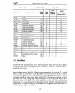
All
of the Intel386 DX microprocessor bus interface pins are summarized in Table
3-1.
3.1
BUS OPERATIONS
There are seven types of bus operations:
• Memory read
• Memory write
• I/O read
• I/O write
• Instruction fetch
• Interrupt acknowledge
• Halt/shutdown
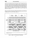
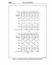
Each bus cycle
is
initiated when the address
is
valid on the address bus, and bus status
pins are driven to states that correspond to the type of bus
cycle,
and
ADS#
is
driven
low.
Status pin states that correspond to each bus
cycle
type are shown in Table 3-2.
Notice that the signal combinations marked
as
invalid states may occur when
ADS#
is
false (high). These combinations
will
never occur if the signals are sampled on the CLK2
rising edge when
ADS#
is
low,
and the Intel386 DX microprocessor internal CLK
is
high (as indicated
by
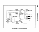
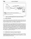
the CLK output of the clock generator circuit shown in
Figure 3-16). Bus status signals must be qualified
withADS#
asserted (low) to identify
the bus cycle.
Memory read and memory write cycles can be locked to prevent another bus master
from using the local bus and allow for indivisible read-modify-write operations.
3-2