I/O INTERFACING
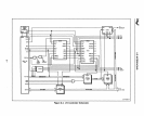
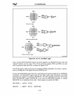
data transceiver. The A2 bit, connected to the 8259A
AO
input, is used
by
the
Intel386 DX microprocessor to distinguish between the two interrupt acknowledge
cycles;
8259A register addresses must therefore be located at two consecutive double-
word boundaries.
When an interrupt occurs, the 8259A activates its Interrupt (INT) output, which
is
con-
nected to the Interrupt Request (INTR) input of the Intel386
DX
microprocessor. The
Intel386
DX
microprocessor automatically executes two back-to-back interrupt-
acknowledge cycles,
as
described in Chapter
3.
The 8259A timing requirements are as
follows:
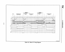
• Each interrupt-acknowledge
cycle
must be extended
by
at least one wait state. Wait-
state generator logic must provide for this extension.
•
Four
idle bus cycles must be inserted between the two interrupt-acknowledge cycles.
The Inte1386 DX microprocessor automatically inserts these idle cycles.
8.5.3.2 CASCADED INTERRUPT CONTROLLERS
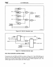
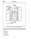
Several 8259As can be cascaded to handle up to
64
interrupt requests. In a cascaded
configuration, one 8259A
is
designated
as
the master controller; it receives input from
the other 8259As, called slave controllers. The interface between the Intel386
DX
micro-
processor and multiple cascaded 8259As
is
an extension of the single-8259A interface
with the following additions:
• The cascade address outputs (CAS2#-CASO#) are output to provide address and
chip-select signals for the slave controllers.
• The interrupt request ljnes (IR7-IRO) of the master controller are connected to the
INT outputs of the slave
controller's,
Each slave controller resolves priority between up to eight interrupt requests and trans-
mits a single interrupt request to the master controller. The master controller, in turn,
resolves interrupt priority between up to eight slave controllers and transmits a single
interrupt request to the Intel386
DX
microprocessor.
The timing of the interface
is
basically the same
as
that of a single
8259A.
During the
first interrupt-acknowledge cycle, all the 8259As freeze the states of their interrupt
request inputs. The master controller outputs the cascade address to select the slave
controller that
is
generating the request with the highest priority. During the second
interrupt-acknowledge cycle, the selected slave controller outputs an interrupt vector to
the Intel386
DX
microprocessor.
Chapter 9 describes the interface to slave controllers that reside on a
MULTIBUS I
systetp bus.
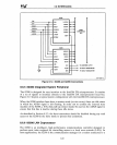
8.5.3.3 HANDLING MORE THAN 64 INTERRUPTS
If
an Inte1386
DX
microprocessor system requires more than
64
interrupt request lines,
a third level of 8259As in polled mode can be added to the configuration described
above. When a third-level controller receives an interrupt request, it drives one of the
8-15


