MULTIBUS I AND Intel386
DX
MICROPROCESSOR
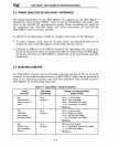
9.3 TIMING ANALYSIS OF MULTIBUS I INTERFACE
The timing specifications for the MULTIBUS I are explained in the MULTIBUS® I
Specification,
Order Number
9800683.
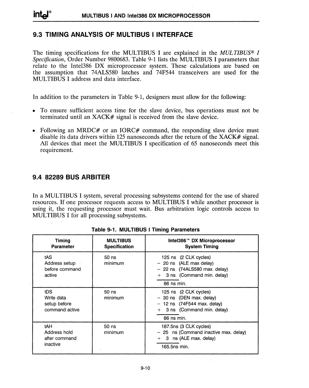
Table
9-1
lists the MULTIBUS I parameters that
relate to the Inte1386
DX
microprocessor system. These calculations are based on
the assumption that 74ALS580 latches and 74F544 transceivers are used for the
MULTIBUS I address and data interface.
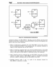
In addition to the parameters in Table 9-1, designers must allow for the following:
• To ensure sufficient access time for the slave device, bus operations must not be
terminated until an XACK# signal
is
received .from the slave device .
• Following an
MRDC#
or an
IORC#
command, the responding slave device must
disable its data drivers within
125
nanoseconds after the return of the XACK# signal.
All devices that meet the
MULTIBUS I specification of
65
nanoseconds meet this
requirement.
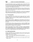
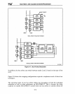
9.4 82289 BUS ARBITER
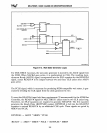
In a MUL TIBUS I system, several processing subsystems contend for the use of shared
resources.
If
one processor requests access to MUL TIBUS I while another processor
is
using it, the requesting processor must wait. Bus arbitration logic controls access to
MULTIBUS I for all processing subsystems.
Table 9-1. MUL TIBUS I Timing Parameters
Timing MULTIBUS InteI386'"
OX
Microprocessor
Parameter
Specification
System Timing
tAS 50 ns 125 ns
(2
ClK
cycles)
Address setup minimum -
20 ns
(ALE
max delay)
before command - 22
ns
(74AlS580 max. delay)
active
+
3ns
(Command min. delay)
,
86
ns min.
tDS
50
ns
125 ns
(2
ClK
cycles)
Write data minimum
-
30ns
(DEN
max. delay)
setup before - 12 ns (74F544
max.
delay)
command active
+
3 ns
(Command min.
delay)
86 ns min.
tAH
50 ns
187.5ns
(3
CLKcycles)
Address hold
minimum
- 25 ns (Command inactive max.
delay)
after command
+
3
ns
(ALE
max. delay)
inactive
165.5ns min.
9-10


