TEST CAPABILITIES
retrieved from the RAM and added to the
12
bits of the Offset field of the linear
address, creating a 32-bit physical address.
If
a miss (no match) occurs, the Intel386
DX
microprocessor must bring the Page Directory and Page Table values into the TLB from
memory.
The Inte1386
DX
microprocessor provides an interface through which to test the TLB.
Two 32-bit test registers of the Inte1386
DX
microprocessor are used to write and read
the contents of the TLB through the
MOV TREG, reg and MOV reg,
TREG
instruc-
tions. An Intel386
DX
microprocessor program can be used to generate test patterns
which are applied to the TLB through automatic test machines or assembly language
programs.
The paging mechanism of the
Intel386DX
microprocessor must be disabled during a
test of the TLB. The internal response
is
therefore not identical to that of normal oper-
ation, but the main functionality of the TLB can be verified.
Test register
#6
is
used
as
the command register for TLB accesses; test register
#7
is
used as the data register. Addresses and commands are written to the TLB through the
command register.
Data
is
read from or written to the TLB through the data register.
The
two
test operations that may be performed on the TLB are:
• Write the physical address contained in the data register and the linear address and
tag bits contained in the command register into a TLB location designed
by
the data
register.
• Look up a TLB entry using the linear address and tag bits contained in the command
register.
If
a hit occurs, copy the corresponding physical address into the data regis-
ter, and set the value of the hit/miss bit in the data register.
If
a miss occurs, clear the
hit/miss bit. In this case, the physical address in the data register
is
undefined.
A command
is
initiated
by
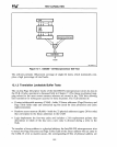
writing to the command register. The command register has
the format shown in Figure 12-2 (top). The two possible commands are distinguished
by
the state of bit 0 in the command register.
If
bit 0 =
1,
a TLB lookup operation
is
performed.
If
bit 0 =
0,
a TLB write
is
performed.
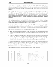
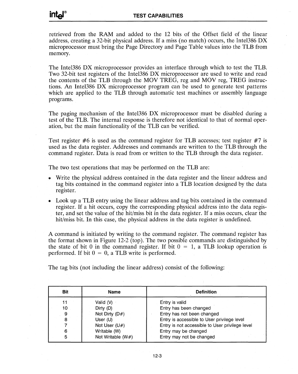
The tag bits (not including the linear address) consist of the following:
Bit Name Definition
11
Valid
(V)
,
Entry
is
valid
10 Oirty (0) Entry has been changed
9 Not Oirty
(0#)
Entry has not been changed
8 User
(U)
Entry
is
accessible to User privilege level
7
Not User (U#)
Entry
is
not accessible to User privilege level
6 Writable
(W)
Entry may be changed
5 Not Writable (W#) Entry may not be changed
12-3


