


l
BE21
H
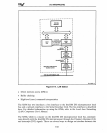
I/O INTERFACING
BEDI
l
l x
Ii
l
BE21
l x
If
L l
'~.
H
Ii
x x
l H
BEll
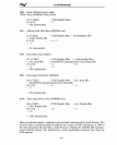
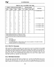
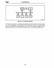
K-map for A 1 signal
BEDI
H
l H
l
x
l
l
BE21
l
.x:
H
l H
:x
H
x x
l
l H
BEll
l l
l
H
l
x l
l
l
l
l
H
l
x
l
l
K-map for
l6-bit
BHE#
signal
BEDI
l H
l
x
l
H
l
l
x l
.H
H
l
l
X'
H
BE
3
1
x x H
.x
l
l H
l
BEll
BE3
[)o---{>o21
Al
I
BEll
---
BEDI
[~
HE
BE31 BE31
----..-
BEll
K-map for lS-bit BlE # signal
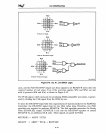
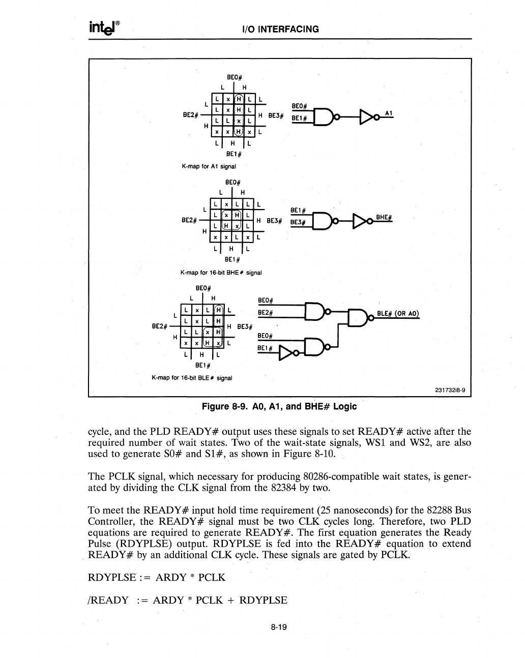
Figure 8-9.
AO,
A 1, and
BHE#
Logic
231732i8-9
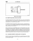
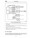
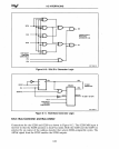
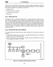
cycle, and the PLD READY # output uses these signals to set READY # active after the
required number of wait states. Two of the wait-state signals, WSI and
WS2,
are also
used to generate
SO#
and
Sl#,:as
shown in Figur\!
8-10.
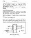
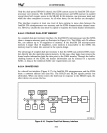
The PCLK signal, which necessary for producing 80286-compatible wait states, isgener-
ated
by
dividing the CLK signal from the
82384
by
two.
To meet the
READY#
input hold time 'requirement
(25
nanoseconds) for the 82288 Bus
Controller, the.
READY#
signal must be two CLK cycles long. Therefore, two PLD
equations are required to generate
READY#.
The first equation generates the Ready
Pulse (RDYPLSE) output. RDYPLSE
is
fed into the READY # equation to extend
READY #
by
an additional CLK
cycle.
These signals are gated
by
PCLK.
RDYPLSE
: = ARDY * PCLK
/READY : = ARDY * PCLK + RDYPLSE
8-19