


LOCAL BUS CONTROL PLD DESCRIPTIONS
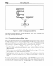
devices requiring different numbers of wait states are in the system, the TIMEDL Y #
state machine must check the chip select wait state pins (CSIWS#, CS3WS#,
,
CS5WS#). These signals are generated from the mapping of the I/O devices. The 8259A
interface has not been built or tested.
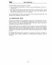
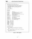
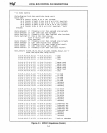
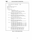
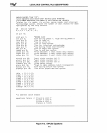
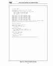
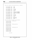
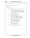
PLD EQUATIONS
The equations for
10PLDI,
IOPLD2, and the RESET/CLOCK PLDs are shown in
Figures
A-I, A-2, and A-3, respectively. These equations are shown
in
a high-level PLD
language (ABEL,
by
Data I/O) that allows the PLD to be described
as
a series of states
rather than equations. This language frees the designer of the tedious task of implement-
ing the state machine and reducing the logical equations manually. The language saves
time not only in the initial design, but also in debugging the state machines. The auto-
mated term reduction of the high-level PLD language allows the designer to explore
many implementations quickly, which
is
a useful feature for complex PLD designs. The
PLD equations generated
by
ABEL are included to allow the conversion to a different
PLD programming language.
A-2