PHYSICAL DESIGN AND DEBUGGING
11.4.3.3 ELECTROSTATIC INTERFERENCE
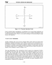
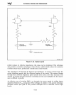
We have discussed two types of coupling, namely inductive and radiative coupling which
are responsible for creating electromagnetic interference. A third, known
as
capacitive
coupling, occurs when
two
equipotential parallel traces are separated
by
a dielectric and
act
as
a,
capacitor. According
to
the standard capacitor equation,
the
electric field
between the two capacitor surfaces varies with the permitivity of the dielectric and with
the area of the parallel conductors.
Electrostatic interference (ESI)
is
caused
by
this type of coupling. The charge built on
one plate of the capacitor induces opposite charge on the other. To minimize the ESI,
the following steps should be taken.
• Separate the signal lines
so
that' the effect of capacitive coupling
is
negated.
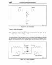
• Run a ground line in between the two lines to cancel the electrostatic fields.
For high-frequency designs, a rule
of
thumb
is
to include ground planes under each
signal layer.
,Ground planes limit the cross-talk caused
by
a capacitive coupling between
small sections of adjacent layers that are at equipotentials. Additionally, when the width
and the thickness
of
signal lines and their distance from the ground
is
constant, the
effect of capacitive coupling upon impedance remains
uniform within ( +
-)
5 percent
across the board. Using fixed impedance does not reduce capacitive coupling, but it does
simplify the modeling of propagation delays and coupling effects.
In
addition, capacitive
coupling can cause interference between layers
so
the wires
sho,uld
be routed orthogo-
nally on neighboring board
layers;
11.4.4 Propagation Delay
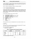
The propagation delay of a circuit is a function of the loads on the line, the impedance,
, and the length of the line segments. The term propagation delay means the propagation
delay in the entire circuit, including the delay in the transmission line (which
is
a func- '
tion of its dielectric constant).
Also, the printed-circuit interconnections add to the propagation delay of the signal on a
wire. These interconnections not only decrease the operating speed of the circuits, but.
also cause reflections which produce undershoot and'overshoot.
.
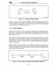
When the propagation delays in a circuit are significant, the design must compensate for
signal skew. Signal skew occurs when the wire lengths (and thus the propagation delays)
between each source and each corresponding load are unequal.
Another negative aspect of propagation delay
is
that it may generate a race condition.
This condition occurs when two signals must reach the same destination within one clock
pulse of one another. To avoid race conditions, it
is
necessary to have the signals travel
through same-length traces.
If
one route
is
shorter, then the signals will arrive at differ-
ent times, causing race conditions.
11-28


