MEMORY INTERFACING
EPLDs have the following additional advantages:
1.
Programmability/erasability allows EPLD functions to be changed easily, simplifying
prototype development.
2.
Since EPLDs are implemented in CMOS technology, they can consume an order of
magnitude less power than bipolar PLDs. Power-conscious applications can benefit
greatly from using EPLDs.
3.
Since the EPROM cell size
is
an order of magnitude smaller than an equivalent
bipolar fuse, EPLDs can implement more functions in the same package. This
higher integration can result in a lower overall component count for a design. The
added flexibility can also mean that an extremely
low
number of "raw" (unpro-
grammed) devices need to be stocked versus bipolar PLDs.
4.
Once an EPLD design has been tested, plastic OTP (One-Time Programmable)
versions of the device can be used in a production environment.
PLDs and EPLDs have the following tradeoffs:
1.
Most PLDs do not have buried (not connected to outputs) registers. For some state
machine applications, this means using an otherwise available output pin to store
the current state.
2.
The drive capability of CMOS EPLDs may be insufficient for some applications.
While the trend
is
towards use of CMOS throughout a system, in cases where high
current levels are required, some additional buffering
is
required with EPLDs.
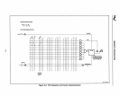
A PLD consists logically of a programmable AND array whose output terms feed a fixed
OR
array. Any sum-of-products equation, within the limits of the number of PLD inputs,
outputs, and equation terms, can be realized
by
specifying the correct AND array con-
nections. Figure
6-2
shows an example of two PLD equations and the corresponding
logic array. Note that every horizontal line in the AND array represents a multi-input
AND gate; every vertical line represents a possible input to the AND gate. An X at the
intersection of a horizontal line and a vertical line represents a connection from the
input to the AND gate.
The sum-of-products
is
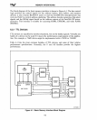
then routed to a configurable macrocell. The macrocell in
Figure
6-3
can be configured
as
a combinational output or registered output. The output
can be active high or active
low.
A separate AND term controls the output buffer.
Designing with PLDs consists of determining where
XS
must be placed in the AND array
and how to configure the macrocell. This task
is
simplified
by
logic compilers, such as
iPLS II (Intel's Programmable Logic Software II) or ABEL. Logic compilers accept
input in the form of sum-of-product equations and translate the input into a JEDEC
programming file that can be used
by
programming hardware/software.
6-4


