


Symbol
t1
t2a
t2b
t3a
t3b
t4
t5
PHYSICAL DESIGN AND DEBUGGING
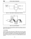
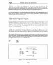
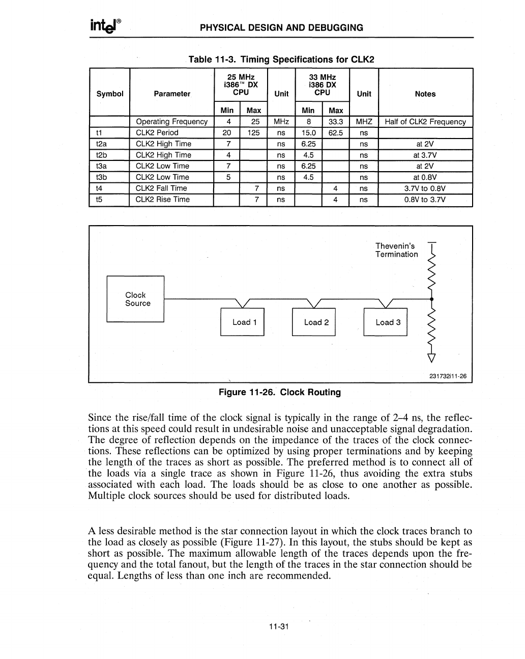
Table 11-3. Timing Specifications
for
CLK2
Parameter
Operating Frequency
CLK2
Period
CLK2 High Time
CLK2 High Time
CLK2 Low Time
CLK2 Low Time
CLK2
Fall Time
CLK2
Rise
Time
Clock
Source
25 MHz 33 MHz
i386'"
OX
1386
OX
CPU
Unit
CPU
Unit
Min
Max Min
Max
4
25
MHz
B 33.3 MHZ
20 125 ns 15.0
62.5
ns
7
ns 6.25 ns
4 ns 4.5
ns
7 ns 6.25
ns
5 ns 4.5 ns
7 ns
4 ns
7 ns 4 ns
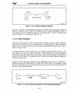
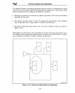
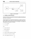
Figure 11-26. Clock Routing
Notes
Half of
CLK2
Frequency
at
2V
at3.7V
at
2V
atO.BV
3.7Vto
O.BV
O.BVto 3.7V
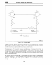
Thevenin's
Termination
231732i11-26
Since the rise/fall time of the clock signal
is
typically in the range of 2-4
ns,
the reflec-
tions at this speed could result in undesirable noise and unacceptable signal degradation.
The degree of
refkction depends on the impedance of the traces of the clock connec-
tions. These reflections can be optimized
by
using proper terminations and by keeping
the length .of the traces
as
short
as
possible. The preferred method
is
to connect all of
the loads via a single trace
as
shown in Figure
11-26,
thus avoiding the extra stubs
associated with each load. The loads should be
as
close to one another
as
possible.
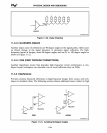
Multiple clock sources should be used for distributed loads.
A less desirable method
is
the star connection layout in which the clock traces branch to
the load
as
closely
as
possible (Figure 11-27). In this layout,
the
stubs should be kept
as
short
as
possible. The maximum allowable length of the traces depends upon the fre-
quency and the total fanout, but the length of the traces in the star connection should be
equal. Lengths of less than one inch are recommended.
11-31