


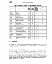
LOCAL BUS INTERFACE
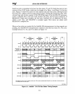
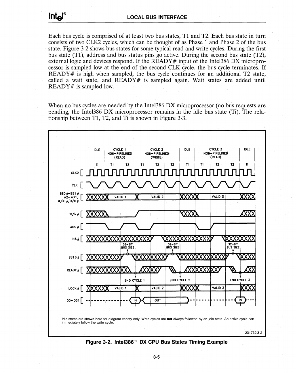
Each bus cycle
is
comprised
of
at least two bus states,
Tl
and T2. Each bus state in turn
consists of
two
CLK2 cycles, which can be thought of
as
Phase 1 and Phase 2 of the bus
state. Figure
3-2
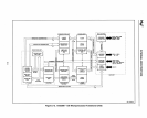
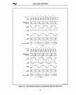
shows bus states for some typical read and write cycles. During the first
bus state
(Tl),
address and bus status pins
go
active. During the second bus state (T2),
external logic and devices respond.
If
the READY # input
of
the Intel386 DX micropro-
cessor
is
sampled low at the end of the second CLK cycle, the bus cycle terminates.
If
READY#
is
high when sampled, the bus cycle continues for an additional T2 state,
called a wait state, and
READY
#
is
sampled again. Wait states are added until
READY
#
is
sampled
low.
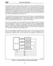
When no bus cycles are needed by the Intel386
DX
microprocessor (no bus requests are
pending, the Intel386
DX
microprocessor remains in the idle bus state (Ti). The rela-
tionship between
Tl,
T2, and Ti
is
shown in Figure 3-3.
CLK2
[
CLK
[
8EO#-8El #
A2-A31.
[
M/IO#.D/CH
W/R#
[
ADS
# [
NA# [
8S16 # [
READY#
[
LOCK#
[
00-
031 [
IDLE
I
CYCLE
1 I
NON-PIPELINED
(READ)
CyCLE
2
NON-PIPELINED
(WRITE)
n
T1
T2
T1
T2
T2
_nIU
rL1l
rtn- rtn-
rtn- rtn-
-V
Y
lr lr lr lr
XX
IX
VALID
1
IX
VALID
2
XIXXXXIX
1/
f\.-
r-
~I
IXXXX
IXXX
XX XX
~xxx
32-BIT
32-BIT
BusllZE
BUSiSIZE
Xl>\X.X.X
l>\X.X.X
y
'(XXXX
XXXXY
XIXXXx
IXXXX
XXX
AM
XXJ
~
TI
rtn-
lr
T1
CYCLE
3
NON-PIPELINED
(READ)
T2 T2
rtfL
rtn-
n.ru
\J
lr lr
xxxxx
VALID
3
,{XXX>"
\-
I
XXX
IXXX
'<XXXX
32-BIT
BUStZE
n
rL1l
V-
~:xxx
~
IXXXX
XXX
IXXX
xx
'<M2S.2!
'(XX
IXXX
XT
~
m
END
CYCLE
1
END
CYCLE
2
END
CYCLE
3
XIXXXXIX
VALID
1
IX
VALID
2
IXXX
IX
VALID
3
IXXXX
-
-----
-----~--~<
OUT
)--
-----
----
--~---
Idle states are shown here for diagram variety only. Write cycles are not always followed
by
an
idle state. An active cycle can
immediately
follow the write cycle.
231732i3-2
Figure 3·2. Inte1386'M
OX
CPU Bus States Timing Example
3-5