


LOCAL BUS INTERFACE
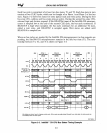
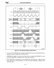
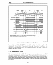
3.1.5 Write Cycle
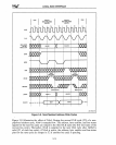
Write cycles, like read cycles, are of two types: pipelined address and non-pipelined
address. Pipelined address cycles are described in Section 3.1.6.
Figure 3-9 shows
two
non-pipelined address write cycles (one with and one without a
wait state. The sequence
of,
signals for a non-pipelined write cycle
is
as
follows:
• The Intel386 DX microprocessor initiates the cycle
by
driving
ADS#
low.
The states
of the address bus (A31-A2), byte enable pins (BE3#-BEO#), and bus status outputs
(M/IO#,
D/C#,
W/R#,
and
LOCK#)
at the CLK edge when
ADS#
is
sampled low
to determine the type of bus cycle to be performed. For a write cycle,
W/R#
is
high
M/IO#
is
high for a memory write,
low
for an I/O write
D/C#
is
high
LOCK#
is
low
if the bus cycle
is
a locked cycle.
In
a read-modify-write sequence,
both the memory data read cycle and the memory data write cycle are locked. No
other bus master should .be permitted to control the bus between
two
locked bus
cycles.
The address bus, byte enable pins, and bus status pins (with the exception of
ADS#)
remain active through the end of the write
cycle.
•
At
the start of Phase 2 in
Tl,
output data becomes valid on the data bus. This data
remains valid until the start of
Phase 2 in
Tl
of the next bus cycle.
.At
the end of T2,
READY
#
is
sampled.
If
READY
#
is
low, the write cycle
terminates.
•
If
READY#
is
not
low,
wait states are added until.
READY#
is
sampled low.
READY #
is
sampled at the end of each wait state.
• Once READY #
is
sampled low, the write
cycle
terminates.
If
a new bus cycle
is
pending, it begins on the next
eLK
cycle.
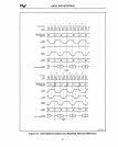
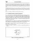
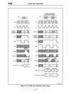
3.1.6 Pipelined Address Cycle
Address pipe lining allows bus cycles to be overlapped, increasing the amount of time
available for the memory or
I/O device to respond. The
NA#
input of the Inte1386
DX
microprocessor controls address pipelining.
NA#
is
generated
by
logic in the system to
indicate that the address bus
is
no longer needed (for example, after the address has
been latched).
If
the system
is
designed so that
NA#
goes active before the end of the
cycle, address pipelining may occur.
NA#
is
sampled at the rising CLK2 edge of Phase 2 of each CLK cycle. Once
NA#
is
sampled active, the address, byte enables, and bus status signals for the next bus cycle
are output as soon
as
they are available internally. Once
NA#
is
sampled active, it
is
not
required again until the CLK cycle after
ADS#
goes active.
3-13