LOCAL BUS INTERFACE
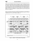
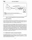
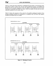
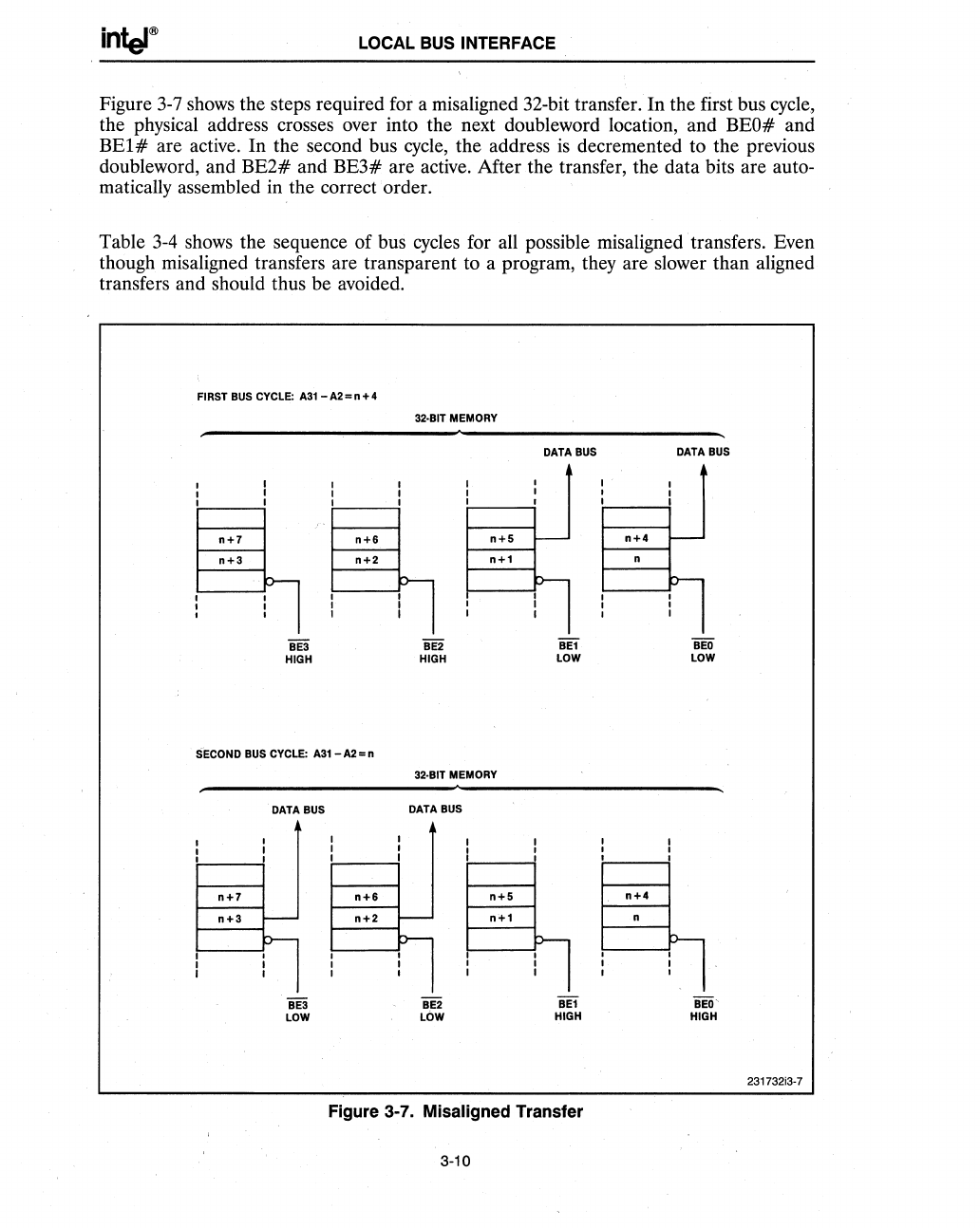
Figure
3-7
shows the steps required for a misaligned 32-bit transfer. In the first bus cycle,
the physical address crosses over into the next doubleword location, and BEO# and
BEl
# are active. In the second bus
cycle,
the address
is
decremented to the previous
doubleword, and
BE2#
and
BE3#
are active. After the transfer, the data bits are auto-
matically assembled in the correct order.
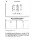
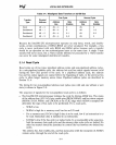
Table
3-4
shows the sequence of bus cycles for all possible misaligned· transfers. Even
though misaligned transfers are transparent to a program, they are slower than aligned
transfers and should thus be avoided.
FIRST BUS CYCLE:
A31
- A2 = n + 4
n+7
n+3
BE3
HIGH
n+6
SECOND BUS CYCLE:
A31
- A2 = n
n+7
n+3
DATA BUS
iE3
LOW
n+8
32·BIT MEMORY
BE2
HIGH
n+5
32·BIT MEMORY
DATA BUS
BE2
LOW
n+5
DATA BUS
BE1
LOW
BE1
HIGH
Figure 3-7. Misaligned Transfer
3-10
n+4
n+4
DATA BUS
BEO
LOW
BEO'
HIGH
231732i3-7


