


SA-1100 Developer’s Manual 9-31
System Control Module
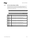
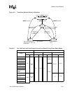
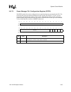
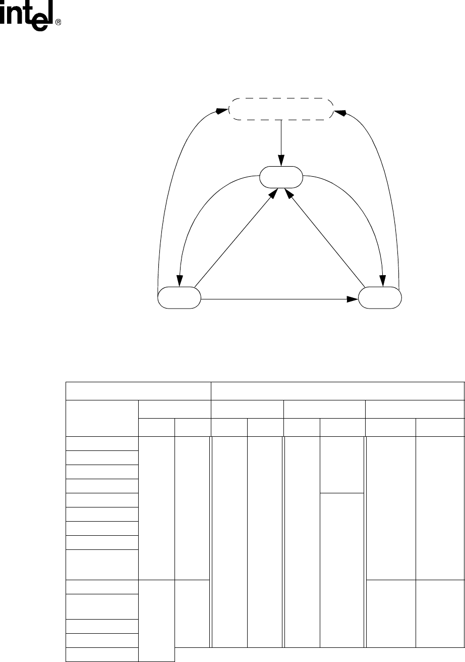
Figure 9-3. Transitions Between Modes of Operation
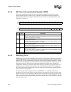
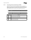
Table 9-2. SA-1100 Power and Clock Supply Sources and States During Power-Down Modes
Power Management Mode
Module
Supply Source Run Idle Sleep
Pwr Clk Pwr Clk Pwr Clk Pwr Clk
CPU
VDD
3.6864
MHz
On Running On
Stopped
Disabled
Stopped
MMUs (I&D)
Write buffer
Read buffer
JTAG
Running
OS timer
LCD controller
Serial channel 0-4
Memory and
PCMCIA
control
Real-time clock
VDDX
32.768
kHz
On
Running
Interrupt
controller
Power manager
General-purpose I/O
Pin pads
IDLE
RUN
SLEEP
Power on, nRESET asserted
nRESET negated
Force sleep bit set, or VDD or
battery fault pins asserted
Wait for interrupt
instruction
Wait for wake-up
event
System or
peripheral unit
interrupt
CPU clock held low; all
other resources active, wait
for interrupt
GPIO or RTC
alarm interrupt
VDD or battery fault
pins asserted
nRESET asserted
nRESET asserted
HARDWARE RESET