


11-188 SA-1100
Developer’s Manual
Peripheral Control Module
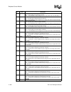
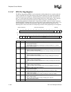
Bit Name Description
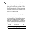
7..0 LDD<7:0
>
LCD data pin state.
Read – Current state of LCD data pin returned.
Write – If LCD disabled and pin configured as an output, drive value to LCD data pin.
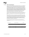
8 L_PCLK
LCD pixel clock pin state.
Read – Current state of LCD pixel clock pin returned.
Write – If LCD disabled and pin configured as an output, drive value to LCD pixel clock pin.
9 L_LCLK
LCD line clock pin state.
Read – Current state of LCD line clock pin returned.
Write – If LCD disabled and pin configured as an output, drive value to LCD line clock pin.
10 L_FCLK
LCD frame clock pin state.
Read – Current state of LCD frame clock pin returned.
Write – If LCD disabled and pin configured as an output, drive value to LCD frame clock pin.
11 L_BIAS
LCD AC bias pin state.
Read – Current state of LCD AC bias pin returned.
Write – If LCD disabled and pin configured as an output, drive value to LCD AC bias pin.
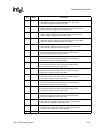
12 TXD1
Serial port 1: SDLC/UART transmit pin state.
Read – Current state of serial port 1 transmit pin returned.
Write – If serial port 1 transmitter disabled and pin configured as an output, drive value
to transmit pin.
13 RXD1
Serial port 1: SDLC/UART receive pin state.
Read – Current state of serial port 1 receive pin returned.
Write – If serial port 1 receiver disabled and pin configured as an output, drive value to
receive pin.
14 TXD2
Serial port 2: IPC transmit pin state.
Read – Current state of serial port 1 transmit pin returned.
Write – If serial port 2 transmitter disabled and pin configured as an output, drive value
to transmit pin.
15 RXD2
Serial port 2: IPC receive pin state.
Read – Current state of serial port 2 receive pin returned.
Write – If serial port 2 receiver disabled and pin configured as an output, drive value to
receive pin.
16 TXD3
Serial port 3: UART transmit pin state.
Read – Current state of serial port 3 transmit pin returned.
Write – If serial port 3 transmitter disabled and pin configured as an output, drive value
to transmit pin.
17 RXD3
Serial port 3: UART receive pin state.
Read – Current state of serial port 3 receive pin returned.
Write – If serial port 3 receive disabled and pin configured as an output, drive value to
receive pin.
18 TXD4
Serial port 4: MCP/SSP transmit pin state.
Read – Current state of serial port 4 transmit pin returned.
Write – If serial port 4 transmitter disabled and pin configured as an output, drive value
to transmit pin.
19 RXD4
Serial port 4: MCP/SSP receive pin state.
Read – Current state of serial port 4 receive pin returned.
Write – If serial port 4 receive disabled and pin configured as an output, drive value to
receive pin.
20 SCLK
Serial port 4: MCP/SSP serial clock pin state.
Read – Current state of serial port 4 serial clock pin returned.
Write – If serial port 4 disabled and pin configured as an output, drive value to serial
clock pin.
21 SFRM
Serial port 4: MCP/SSP serial frame pin state.
Read – Current state of serial port 4 serial frame pin returned.
Write – If serial port 4 disabled and pin configured as an output, drive value to serial
frame pin.
31..22 —
Reserved.