9-22 SA-1100
Developer’s Manual
System Control Module
9.4.1 OS Timer Count Register (OSCR)
The OS timer count register is a 32-bit counter that increments on rising edges of the 3.6864-MHz
clock. This counter can be read or written at any time. It is recommended that the system
write-protect this register through the MMU protection mechanisms.
9.4.2 OS Timer Match Registers 0–3 (OSMR<0>, OSMR<1>,
OSMR<2>, OSMR<3>)
These registers are 32 bits wide and are readable and writable by the processor. They are compared
against the OSCR following every rising edge of the 3.6864-MHz clock. If any of these registers
match the counter at this time, then the corresponding status bit in the OSSR is set. The status bits
are routed to the interrupt controller where they can be unmasked to cause a CPU interrupt.
OSMR<3> may also serve as a watchdog timer. See the Section 9.4.6, “Watchdog Timer” on
page 9-24 for operation information.
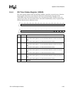
9.4.3 OS Timer Watchdog Match Enable Register (OWER)
The watchdog enable register contains a single control bit (bit 0) that enables the watchdog
function. This bit is set by writing a one to it. It can only be cleared by one of the reset functions
(hardware reset, software reset) and by entering sleep mode. A watchdog reset also clears the
watchdog enable bit. The format of this register follows:
.
Bit31302928272625242322212019181716
R/W Reserved
Reset0000000000000000
Bit1514131211109876543210
R/W Reserved WME
Reset0000000000000000
Bit Name Description
0WME
Watchdog match enable.
0 – OS timer match register<3> matches cause an interrupt request.
1 – OS timer match register<3> matches cause a reset of the
SA-1100.
Note: This is a write-once bit that once written, can only be changed after a hardware
(pin), software (SWR), or sleep mode reset.
31..1 — Reserved.


