9-18 SA-1100
Developer’s Manual
System Control Module
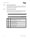
9.3.2 RTC Alarm Register (RTAR)
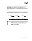
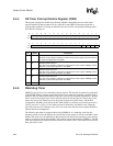
The real-time clock alarm register is a 32-bit register that is readable and writable by the processor.
Following each rising edge of the 1-Hz clock, this register is compared to the RCNR. If the two are
equal and the enable bit is set, then the alarm bit in the RTC status register is set. The value in this
register is undefined after the assertion of nRESET.
9.3.3 RTC Status Register (RTSR)
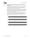
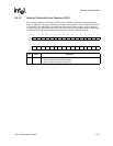
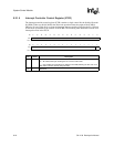
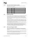
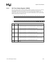
The following table shows the location of all bits in the RTSR. All reserved bits are read as zeros
and are unaffected by writes; a question mark indicates that the value is unknown at reset. The AL
and HZ bits in this register are routed to the interrupt controller where they may be enabled to
cause an interrupt. The AL and HZ bits are cleared by writing ones to them.
.
Bit31302928272625242322212019181716
R/W Reserved
Reset0000000000000000
0
Bit1514131211109876543210
R/W Reserved HZE ALE HZ AL
Reset000000000000????
Bit Name Description
0AL
RTC alarm detected.
0 – No alarm has been detected.
1 – An alarm has been detected (RTNR matches RCAR).
1HZ
1-Hz rising-edge detected.
0 – No rising edge has been detected.
1– A rising edge has been detected.
2ALE
RTC alarm interrupt enable.
0 – The RTC alarm interrupt is not enabled.
1 – The RTC alarm interrupt is enabled.
3HZE
1-Hz interrupt enable.
0 – The 1-Hz interrupt is not enabled.
1 – The 1-Hz interrupt is enabled.
31..4 —
Reserved.


