


SA-1100 Developer’s Manual 9-3
System Control Module
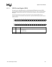
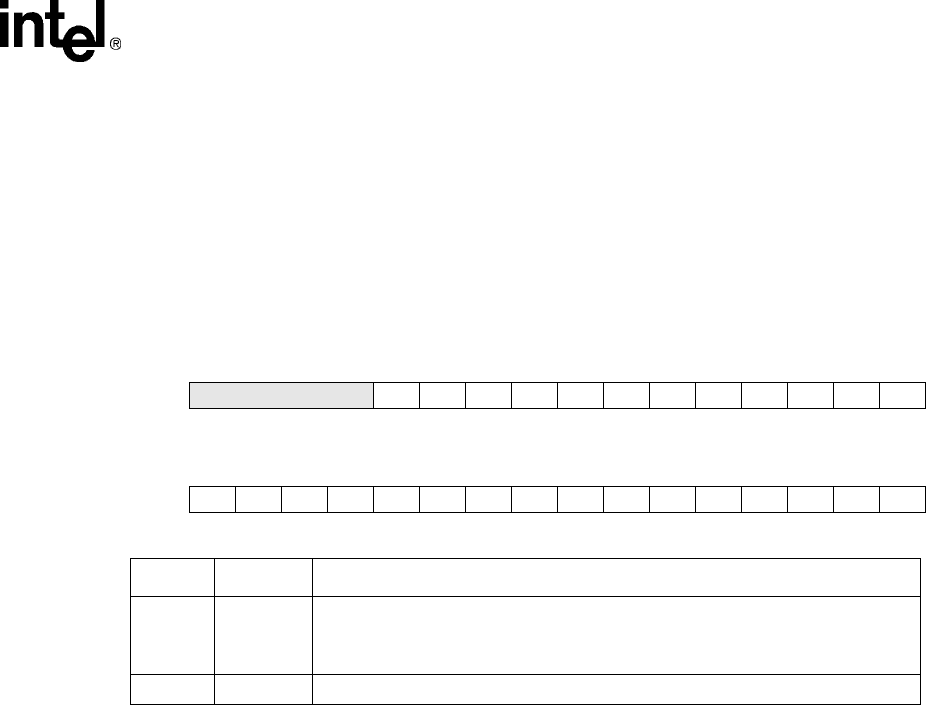
9.1.1.1 GPIO Pin-Level Register (GPLR)
The state of each of the GPIO port pins is visible through the GPIO pin-level register (GPLR).
Each bit number corresponds to the port pin number from bit 0 to bit 27. This is a read-only register
that is used to determine the current level of a particular pin (regardless of the programmed pin
direction).
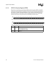
The following table shows the locations of the 28 pin-level bits within the GPLR. This is a
read-only register. For reserved bits, reads return zero; a question mark indicates that the values are
unknown at reset.
Bit31302928272625242322212019181716
Read Reserved PL27 PL26 PL25 PL24 PL23 PL22 PL21 PL20 PL19 PL18 PL17 PL16
Reset0000????????????
--
Bit1514131211109876543210
Read PL15 PL14 PL13 PL12 PL11 PL10 PL9 PL8 PL7 PL6 PL5 PL4 PL3 PL2 PL1 PL0
Reset????????????????
Bit Name Description
{n} PL{n}
GPIO port pin level n (where n = 0 through 27).
0 – Pin state is low.
1 – Pin state is high.
31.. 28 — Reserved.