


SA-1100 Developer’s Manual 2-1
Functional Description
2
This chapter provides a functional description of the Intel
®
StrongARM
®
SA-1100 Microprocessor
(SA-1100). It describes the basic building blocks within the processor, lists and describes the pins,
and explains the memory map.
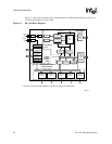
2.1 Block Diagram
The SA-1100 consists of the following functional blocks:
• Processor
The processor is the ARM™
SA-1 core with a 16 Kbyte instruction and 8 Kbyte data cache
(Dcache). The instruction (I) and data (D) streams are translated through independent
memory-management units (MMUs). Stores are made using a four-line write buffer. The
performance of specialized load routines is enhanced with the four-entry read buffer that can be
used to prefetch data for use at a later time. A 16-entry minicache provides a smaller and logically
separate data cache that can be used to enhance caching performance when dealing with large data
structures.
• Memory and PCMCIA controller
The memory and PCMCIA control module (MPCM) supports four banks of standard or EDO DRAM
on a 32-bit data width. ROM (standard and burst), Flash memory, and SRAM are also supported.
ROM and Flash can be either 16 or 32 bits wide. SRAM width is limited to 32 bits. Expansion devices
are supported through PCMCIA control signals that share the memory bus data and address lines to
complete the card interface. Some external glue logic (buffers and transceivers) is necessary to
implement the interface. Control is provided to permit two card slots with hot-swap capability.
• Peripherals
The peripheral control module (PCM) contains a number of serial control devices, an LCD
controller as well as a six-channel DMA controller to provide service to these devices:
– An LCD controller with support for passive or active displays
– A universal serial bus (USB) endpoint controller
– An SDLC communications controller
– A serial controller with supporting 115 Kbps and 4 Mbps IrDA protocols
– A 16550-like UART supporting 230 Kbps
– A CODEC interface supporting SPI, µWire, TI, UCB1100, and UCB1200
• General system control functions
The system control module (SCM) is also connected to the peripheral bus. It contains five blocks
used for general system functions:
– A real-time clock (RTC) clocked from an independent 32.768 kHz oscillator
– An operating system timer (OST) for general system timer functions as well as a watchdog mode
– Twenty-eight general-purpose I/Os (GPIO)
– An interrupt controller
– A power-management controller that handles the transitions in and out of sleep and idle modes
– A reset controller that handles the various reset sources on the processor