


SA-1100 Developer’s Manual 11-83
Peripheral Control Module
If the user disables the receiver during operation, reception of the current data byte is stopped
immediately, the serial shifter and receive FIFO are cleared, control of the RXD1 pin is given to
the peripheral pin control (PPC) unit, and all clocks used by the receive logic are automatically shut
off to conserve power. However, the transmitter continues to function as normal.
11.9.1.9 Transmit Operation
The SDLC transmit logic can operate at the same time as the receive logic (full-duplex). The user
may either “prime” the transmit FIFO by filling it with data or allow service requests to cause the
CPU or DMA to fill the FIFO once the SDLC transmitter is enabled. Once enabled, the transmit
logic issues a service request if its FIFO is empty. Flags are transmitted continuously until valid
data resides within the FIFO. Once a byte of data resides at the bottom of the transmit FIFO, it is
transferred to the serial shifter. It is encoded and shifted out onto the TXD1 pin clocked by the
programmed baud rate clock. Note that the flag and CRC value are automatically transmitted and
need not be placed in the transmit FIFO.
When the transmit FIFO is emptied halfway, an interrupt and/or DMA service request is signalled. If
new data is not supplied soon enough, the FIFO is completely emptied and the transmit logic attempts
to take additional data from the empty FIFO. The user can program one of two actions: an underrun to
signal the normal completion of a frame or an unexpected termination of a frame in progress.
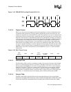
When normal frame completion is selected and an underrun occurs, the transmit logic transmits the
16-bit CRC value calculated during the transmission of all data within the frame (including the
address and control bytes), followed by a flag to denote the end of the frame. The transmitter then
continuously transmits flags until data is once again available within the FIFO. Once data is
available, the transmitter begins transmission of the next frame.
When unexpected frame termination is selected and an underrun occurs, the transmit logic outputs
an abort and interrupts the CPU. An abort continues to be transmitted until data is once again
available in the transmit FIFO. The SDLC then transmits a flag and starts the new frame. The
off-chip receiver can choose to ignore the abort and continue to receive data, or to signal serial port
1 to retry transmission of the aborted frame.
If the user disables the transmitter during operation, transmission of the current data byte is stopped
immediately, the serial shifter and transmit FIFO are cleared, control of the TXD1 pin is given to
the peripheral pin control (PPC) unit, and all clocks used by the transmit logic are automatically
shut off to conserve power. However, the receiver continues to function as normal.
11.9.1.10 Simultaneous Use of the UART and SDLC
Serial port 1 contains a control bit to select which serial protocol to use: SDLC or UART. Note that
the two protocols cannot be combined at the same time (SDLC transmit and UART receive).
However, since the SDLC and UART are fully independent blocks, a mode is supported that allows
the user to enable the SDLC using serial port 1’s pins (TXD1 and RXD1) while the UART is
enabled using two GPIO pins (GPIO<14> for transmit and GPIO<15> for receive operation). This
mode is enabled by setting the UART pin reassignment (UPR) control bit within the peripheral pin
controller (PPC). See the Section 11.13, “Peripheral Pin Controller (PPC)” on page 11-184. Note
that when this mode is enabled, serial port 1’s control bit, which selects SDLC versus UART
operation, is ignored and serial port 1 defaults to SDLC mode.