11-78 SA-1100
Developer’s Manual
Peripheral Control Module
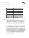
11.8.14 UDC Register Locations
Table 11-13 shows the registers associated with the UDC and the physical addresses used to access them.
11.9 Serial Port 1 – SDLC/UART
Serial port 1 is a combination synchronous data link controller (SDLC) and universal asynchronous
receiver/transmitter (UART) serial controller. The user can configure it to perform one of the two
functions, but operation of both modes using serial port 1’s pins cannot occur simultaneously
(SDLC transmit and UART receive). However, the peripheral pin control (PPC) unit can be
configured to take control of two GPIO pins and use them for UART transmission, while serial
port 1’s pins are used for SDLC operation. See the Section 11.13, “Peripheral Pin Controller
(PPC)” on page 11-184 for a description of how the PPC is configured to allow use of both the
SDLC and UART.
For both protocols, serial port 1 can operate at baud rates from 56.24 bps to 230.4 Kbps. Both also
contain an 11-bit wide by 12-entry deep receive FIFO and an 8-bit wide by 8-entry deep transmit
FIFO to buffer incoming and outgoing data, respectively. The FIFOs can be filled or emptied either
by the DMA or the CPU, with service requests being signalled when the transmit FIFO is
half-empty and the receive FIFO is one- to two-thirds full.
Used as an SDLC controller, serial port 1 supports much of the functionality found in commercial
serial communications controllers, such as the 85C30. Frames contain an 8-bit address, an optional
control field, a data field of any size that is a multiple of 8 bits, and a 16-bit CRC-CCITT. The start
and stop flags and CRC generation and checking are handled automatically. Data can be selectively
saved in the receive FIFO by programming an address with which to compare against all incoming
frames. Interrupts are signalled when CRC checks performed on received data indicate an error,
when a receiver abort occurs, when the transmit or receive FIFO needs to be filled or emptied,
when the transmit FIFO underruns during an active frame and is aborted, when the receive FIFO
overruns and data is lost, and when the last byte of data within a frame is contained within the
bottom four entries of the receive FIFO.
Table 11-13. UDC Control, Data, and Status Register Locations
Address Name Description
0h8000 0000 UDCCR UDC control register
0h8000 0004 UDCAR UDC address register
0h8000 0008 UDCOMP UDC OUT max packet register
0h8000 000C UDCIMP UDC IN max packet register
0h8000 0010 UDCCS0 UDC endpoint 0 control/status register
0h8000 0014 UDCCS1 UDC endpoint 1 (OUT) control/status register
0h8000 0018 UDCCS2 UDC endpoint 2 (IN) control/status register
0h8000 001c UDCD0 UDC endpoint 0 data register
0h8000 0020 UDCWC UDC endpoint 0 write count register
0h8000 0024 — Reserved
0h8000 0028 UDCDR UDC transmit/receive data register (FIFOs)
0h8000 002c — Reserved
0h8000 0030 UDCSR UDC status/interrupt register


