


SA-1100 Developer’s Manual 11-95
Peripheral Control Module
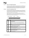
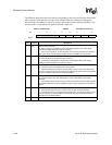
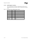
The following table shows the bit locations corresponding to the data field and end-of-frame bit as
well as the cyclic redundancy check and receiver overrun error bits within the SDLC data register.
Note that both FIFOs are cleared when the SA-1100 is reset, the transmit FIFO is cleared when
writing TXE=0, and the receive FIFO is cleared when writing RXE=0.
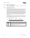
Address: 0h 8002 0078 SDDR Read/Write
Bit 109876543210
ROR CRE EOF Bottom of Receive FIFO Data
Reset00000000000
Read Access
Note: ROR, CRE, EOF are not read, but rather are transferred to corresponding status bits in SDSR1
each time a new data value is transferred to SDDR.
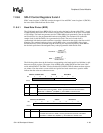
Bit 76543210
Top of Transmit FIFO Data
Reset 00000000
Write Access
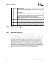
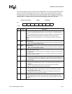
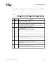
Bit Name Description
7..0 DATA
Top/bottom of transmit/receive FIFO data.
Read – Bottom of receive FIFO.
Write – Top of transmit FIFO.
8EOF
End of frame.
0 – The last byte of the frame has not been encountered.
1– The data value at the bottom of the receive FIFO represents the last byte of the frame.
Note: Each time an 11-bit value reaches the bottom of the receive FIFO, bit 8 from the
last FIFO entry is transferred to the EOF bit in SDSR1.
9CRE
CRC error.
0 – CRC not encountered yet, or the CRC value calculated on the incoming data
matched the received CRC value.
1 – The CRC value calculated on the incoming data did not match the received CRC
value.
Note: Each time an 11-bit value reaches the bottom of the receive FIFO, bit 9 from the
last FIFO entry is transferred to the CRE bit in SDSR1.
10 ROR
Receiver overrun.
0 – No receiver overrun has been detected.
1 – Receive logic attempted to place data into receive FIFO while it was full; one or more
data values
after
the data value at the bottom of the receive FIFO were lost.
Note: Each time an 11-bit value reaches the bottom of the receive FIFO, bit 10 from the
last FIFO entry is transferred to the ROR bit in SDSR1.