11-26 SA-1100
Developer’s Manual
Peripheral Control Module
11.7.3 LCD Controller Control Register 0
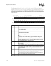
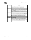
LCD controller control register 0 (LCCR0) contains 10 bit fields that are used to control various
functions within the LCD controller.
11.7.3.1 LCD Enable (LEN)
The LCD enable (LEN) bit is used to enable and disable all LCD controller operation. When
LEN=0, the LCD controller is disabled and control of all 12 of its pins is given to the peripheral pin
controller (PPC) unit to be used as general-purpose I/O (noninterruptible). When LEN=1, the LCD
controller is enabled. Note that all other control registers should be initialized before setting LEN.
The user can program LCCR0 last, and configure all 10 bit fields at the same time via a word write
to the register. If the user clears LEN while the LCD controller is enabled, it will complete
transmission of the current frame before being disabled. Completion of the current frame is
signalled by the LCD when it sets the LCD disable done flag (LDD) within the LCD status register
that generates an interrupt request. The user should use a read-modify-write procedure to clear
LEN because the other bit-fields within LCCR0 continue to be used by the LCD controller after
LEN is cleared until the frame that is currently in progress completes. When the LCD controller is
disabled, control of all 12 of its pins is given to the peripheral pin controller (PPC) so that they may
be used for general-purpose input and output (noninterruptible). See the Section 11.13, “Peripheral
Pin Controller (PPC)” on page 11-184 for a description of the PPC.
11.7.3.2 Color/Monochrome Select (CMS)
The color/monochrome select (CMS) bit selects whether the LCD controller operates in color or
monochrome mode. When CMS=0, color mode is selected, palette entries are 12 bits wide (4 bits
per color), 8 data pins are enabled for single-panel mode, 16 data pins are enabled for dual-panel
mode (GPIO pins 2..9 are used as the extra 8 data output pins), and all three dither blocks are used,
one each for the red, green, and blue pixel components. When CMS=1, monochrome mode is
selected, palette entries are 4 bits wide (15 levels of gray-scale), 4 or 8 data pins are enabled for
single-panel mode, and 8 data pins are enabled for dual-panel mode.
11.7.3.3 Single-/Dual-Panel Select (SDS)
In passive mode (PAS=0), the single-/dual-panel select (SDS) bit is used to select the type of
display control that is implemented by the LCD screen. When SDS=0, single-panel operation is
selected (pixels presented to screen a line at a time), and when SDS=1, dual-panel operation is
selected (pixels presented to screen two lines at a time). Single-panel LCD drivers have one
line/row shifter and driver for pixels, and one line pointer; dual-panel LCD controller drivers have
two line/row shifters (one for the top half of the screen, one for the bottom), and two line pointers
(one for the top half of the screen, one for the bottom). When dual-panel mode is programmed,
both of the LCD controller’s DMA channels are used. DMA channel 1 is used to load the palette
RAM from the frame buffer and to drive the upper half of the display, and DMA channel 2 drives
the lower half. The two channels alternate when fetching data for both halves of the screen, placing
encoded pixel values within the two separate input FIFOs. When programming dual-panel
operation, the user must perform the following sequence in order: disable the LCD (LEN=0),
program dual-panel mode (SDS=0->1), write the upper panel DMA base address, write the lower
panel DMA base address, and enable the LCD (LEN=0->1). When dual-panel operation is enabled,
the LCD controller doubles its pin uses; thus, for monochrome screens 8 pins are used, and for
color screens, 16 pins are used.


