SA-1100 Developer’s Manual 11-63
Peripheral Control Module
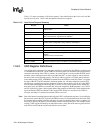
Table 11-12 shows a summary of all device requests. Users should refer to the Universal Serial Bus
Specification Revision 1.0 for a full description of host device requests.
11.8.2 UDC Register Definitions
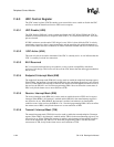
All configuration, request/service, and status reporting is controlled by the USB host controller and
is communicated to the UDC via the USB bus. Several registers are available to the programmer to
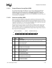
control the interfacing of the UDC to software. A control register is used to enable the UDC and to
mask the various interrupt sources that exist within the UDC. A status register is used to indicate
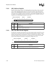
the state of the various interrupt sources. The device address register is available, which software
writes when parsing a SET_ADDRESS command from the USB host controller. There is a register
for each of the OUT and IN endpoints’ maximum packet size. All three endpoints (control, OUT,
and IN) have a control/status register. Endpoint 0 (control) has an address for the 8 x 8 data FIFO
used for both transmitting and receiving data, as well as a write count register used to determine
how many bytes the USB host controller has sent to the endpoint 0. Both endpoints 1 and 2 (OUT
and IN, respectively) share a data register address that contains an 8-bit field, which addresses the
top of the transmit FIFO and bottom of the receive FIFO. When it is read, the receive FIFO is
accessed, and when it is written, the transmit FIFO is accessed.
Note: Due to the internal synchronization required by the UDC’s configuration registers, it is possible for
the processor to write the UDC registers and FIFOs too fast. It is required that all writes to the UDC
be complete before another write may take place. In order to guarantee that a write is complete, it is
necessary to observe the effect of a write before another write may take place. For example, when
writing a UDC register followed by an immediate read to verify data in the same register, the first
read will be invalid and the second read will have correct data.
Table 11-12. Host Device Request Summary
Request Name
SET_FEATURE Used to enable a specific feature such as device remote wake-up and
endpoint stalls.
CLEAR_FEATURE Used to clear or disable a specific feature.
SET_CONFIGURATION Configures the UDC for operation. Used following a reset of the SA-1100 or
after a reset has been signalled via the USB bus.
GET_CONFIGURATION Returns the current UDC configuration to the host.
SET_DESCRIPTOR Used to set existing descriptors or add new descriptors. Existing descriptors
include: device, configuration, string, interface, and endpoint.
GET_DESCRIPTOR Returns the specified descriptor if it exists.
SET_INTERFACE Used to select an alternate setting for the UDC’s interface.
GET_INTERFACE Returns the selected alternate setting for the specified interface.
GET_STATUS Returns the UDC’s status including: remote wake-up, self-powered, data
direction,
endpoint number, and stall status.
SET_ADDRESS Sets the UDC’s 7-bit address value for all future device accesses.
SYNCH_FRAME Used to set and then report an endpoint’s synchronization frame.


