


SA-1100 Developer’s Manual xvii
Figures
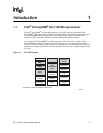
1-1 SA-1100 Features.............................................................................................. 1-1
1-2 SA-1100 Example System................................................................................. 1-5
2-1 SA-1100 Block Diagram .................................................................................... 2-2
2-2 SA-1100 Functional Diagram............................................................................. 2-3
2-3 SA-1100 Memory Map....................................................................................... 2-8
5-1 Format of Internal Coprocessor Instructions MRC and MCR ............................ 5-1
9-1 General-Purpose I/O Block Diagram ................................................................. 9-2
9-2 Interrupt Controller Block Diagram .................................................................. 9-11
9-3 Transitions Between Modes of Operation........................................................ 9-31
10-1 General Memory Interface Configuration........................................................ 10-1
10-2 Example Memory Configuration ...................................................................... 10-3
10-3 DRAM Single-Beat Transactions................................................................... 10-16
10-4 DRAM Burst-of-Eight Transactions................................................................ 10-17
10-5 DRAM Refresh Cycle..................................................................................... 10-18
10-6 Burst-of-Eight ROM Timing Diagram............................................................. 10-20
10-7 Eight Beat Burst Read from Burst-of-Four ROM ........................................... 10-21
10-8 Nonburst ROM, SRAM, or Flash Read Timing Diagram – Four Data Beats . 10-21
10-9 SRAM Write Timing Diagram (4–Beat Burst) ................................................ 10-22
10-10 Flash Write Timing Diagram (2 Writes).......................................................... 10-24
10-11 PCMCIA Memory Map................................................................................... 10-26
10-12 PCMCIA External Logic for a Two-Socket Configuration .............................. 10-29
10-13 PCMCIA External Logic for a One-Socket Configuration .............................. 10-30
10-14 PCMCIA Voltage-Control Logic ..................................................................... 10-31
10-15 PCMCIA Memory or I/O 16-Bit Access.......................................................... 10-32
10-16 PCMCIA I/O 16-Bit Access to 8-Bit Device.................................................... 10-33
11-1 Peripheral Control Module Block Diagram....................................................... 11-2
11-2 Big and Little Endian DMA Transfers............................................................... 11-9
11-3 Palette Buffer Format..................................................................................... 11-19
11-4 4 Bits Per Pixel Data Memory Organization (Little Endian) ........................... 11-20
11-5 8-Bits Per Pixel Data Memory Organization (Little Endian)........................... 11-21
11-6 12-Bits Per Pixel Data Memory Organization (Passive Mode Only).............. 11-21
11-7 16-Bits Per Pixel Data Memory Organization (Active Mode Only)................. 11-21
11-8 LCD Data-Pin Pixel Ordering......................................................................... 11-28
11-9 Frame Buffer/Palette Bits Output to LCD Data Pins in Active Mode ............. 11-30
11-10 Passive Mode Beginning-of-Frame Timing.................................................... 11-51
11-11 Passive Mode End-of-Frame Timing ............................................................. 11-52
11-12 Passive Mode Pixel Clock and Data Pin Timing............................................ 11-53
11-13 Active Mode Timing ....................................................................................... 11-54
11-14 Active Mode Pixel Clock and Data Pin Timing............................................... 11-55
11-15 NRZI Bit Encoding Example .......................................................................... 11-58
11-16 IN, OUT, and SETUP Token Packet Format ................................................. 11-60
11-17 SOF Token Packet Format............................................................................ 11-60
11-18 Data Packet Format....................................................................................... 11-60
11-19 Handshake Packet Format ............................................................................ 11-60
11-20 Bulk Transaction Formats.............................................................................. 11-61
11-21 Control Transaction Formats ......................................................................... 11-62
11-22 FM0/NRZ Bit Encoding Example (0100 1011)............................................... 11-80
11-23 SDLC Frame Format ..................................................................................... 11-80