


SA-1100 Developer’s Manual 10-3
Memory and PCMCIA Control Module
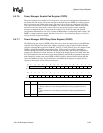
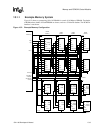
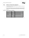
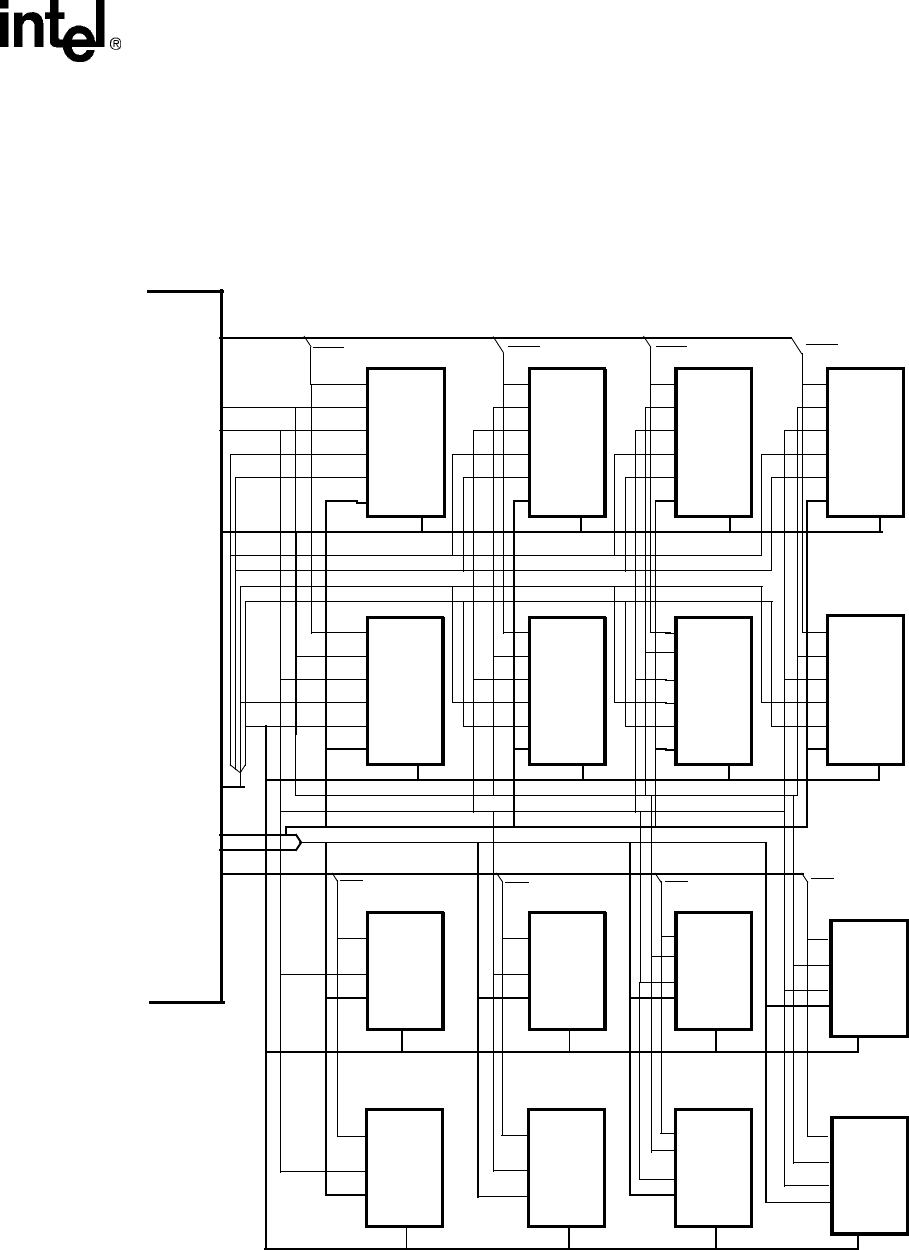
10.1.1 Example Memory System
Figure 10-2 shows a system using 1M x 16 DRAMs for a total of 16 Mbyte of DRAM. Two banks
of ROM and two banks of Flash EPROM are shown, each on a 32-bitwide databus. The PCMCIA
interface is not shown.
Figure 10-2. Example Memory Configuration
nRAS<3:0>
nWE
2 Mbyte
(x16)
RAS
WE
OE
UCAS
LCAS
A11-0
D15-0
RAS
WE
OE
UCAS
LCAS
A11-0D15-0
RAS
WE
OE
UCAS
LCAS
A11-0D15-0
RAS
WE
OE
UCAS
LCAS
A11-0
D15-0
RAS
WE
OE
UCAS
LCAS
A11-0D15-0
RAS
WE
OE
UCAS
LCAS
A11-0 D15-0
RAS
WE
OE
UCAS
LCAS
A11-0 D15-0
RAS
WE
OE
UCAS
LCAS
A11-0
D15-0
DRAM
CE
OE
A22-0
D15-0
16-bit
CE
OE
A22-0
D15-0
16-bit
CE
OE
A22-0
D15-0
EPROM
WE
OE
A22-0
WE
CE
16-bit
nCS<3:0>
A21/DRA11-
A25-22,A9-0
A10/DRA0
A24-2
DRA11-0
nCAS<3:0>
CAS0
CAS1
CAS3
CAS2
D31-0
D31-16
D15-0
D31-16
D15-0
FLASH
FLASH
RAS0
RAS1
RAS2
RAS3
CS3
CS2
CS1
CS0
EPROM
ROM
CE
OE
A22-0
D15-0
ROM
CE
OE
A22-0
D15-0
16-bit
CE
OE
A22-0
D15-0
EPROM
WE
OE
A22-0
WE
CE
D15-0
FLASH
16-bit
FLASH
EPROM
D15-0
nOE
DRAM
DRAM
DRAM
DRAM
BANK 0
BANK 1 BANK 2
BANK 3
ROM BANK 0
ROM BANK 1
FLASH BANK 0
FLASH BANK 1
ROM
ROM
16-bit
16-bit
16-bit ROM
16-bit