SA-1100 Developer’s Manual 9-43
System Control Module
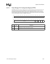
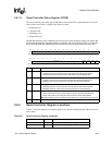
9.6.1.2 Reset Controller Status Register (RCSR)
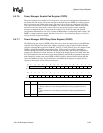
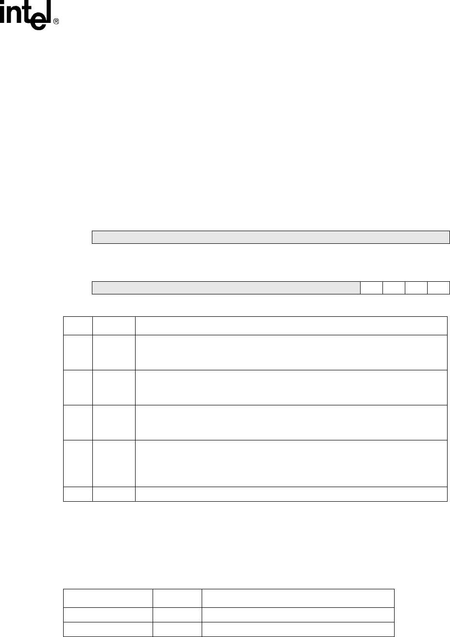
The reset controller reset status register (RCSR) is used by the CPU to determine the last cause or
causes of the reset. The SA-1100 has four sources of reset:
• Hardware reset
• Software reset
• Watchdog reset
• Sleep mode reset
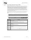
Each RCSR status bit is set by a different source of reset, and can be cleared by writing a one back to that
bit. Note that the hardware reset state of software, watchdog, and sleep mode reset bits is zero. The table
below shows the status bits within RCSR. For reserved bits, writes are ignored and reads return zero.
9.6.2 Reset Controller Register Locations
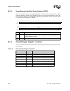
Table 9-5 shows the registers associated with the reset controller and the physical addresses used to
access them.
Bit31302928272625242322212019181716
R/W Reserved
Reset0000000000000000
Bit1514131211109876543210
R/W Reserved SMR WDR SWR HWR
Reset0000000000000001
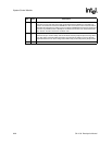
Bit Name Description
0HWR
Hardware reset.
0 – Hardware reset has not occurred since the last time the CPU cleared this bit.
1 – Hardware reset has occurred since the last time the CPU cleared this bit.
1SWR
Software reset.
0 – Software reset has not occurred since the last time the CPU cleared this bit.
1 – Software reset has occurred since the last time the CPU cleared this bit.
2WDR
Watchdog reset.
0 – Watchdog reset has not occurred since the last time the CPU cleared this bit.
1 – Watchdog reset has occurred since the last time the CPU cleared this bit.
3SMR
Sleep mode reset.
0 – Sleep mode reset has not occurred since the last time the CPU cleared this bit.
1 – Sleep mode reset has occurred since the last time the CPU cleared this bit.
Note: Each status flag can be cleared only by reading a one and then writing a zero to it.
31..4 — Reserved.
Table 9-5. Reset Controller Register Locations
Address Name Description
0h 9003 0000 RSRR Reset controller software reset register
0h 9003 0004 RCSR Reset controller status register


