16-6 SA-1100
Developer’s Manual
Boundary-Scan Test Interface
16.6.2 SA-1100 Device Identification (ID) Code Register
Purpose: This register is used to read the 32-bit device identification code. No programmable
supplementary identification code is provided.
Length: 32 bits
Operating Mode: When the IDCODE instruction is current, the ID register is selected as the serial
path between TDI and TDO.
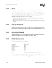
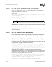
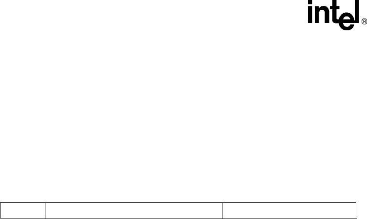
The format of the ID register is as follows:
The high-order 4 bits of the ID register contains the version number of the silicon and changes with
each new revision.
There is no parallel output from the ID register.
The 32-bit device identification code is loaded into the ID register from its parallel inputs during
the CAPTURE-DR state.
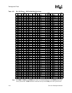
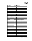
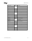
16.6.3 SA-1100 Boundary-Scan (BS) Register
Purpose: The BS register consists of a serially connected set of cells around the periphery of the
device, at the interface between the core logic and the system input/output pads. This register can
be used to isolate the pins from the core logic and then drive or monitor the system pins.
Operating Modes: The BS register is selected as the register to be connected between TDI and
TDO only during the SAMPLE/PRELOAD and EXTEST instructions. Values in the BS register
are used, but are not changed, during the CLAMP instruction.
In the normal (system) mode of operation, straight-through connections between the core logic and
pins are maintained, and normal system operation is unaffected.
In TEST mode (when EXTEST is the currently selected instruction), values can be applied to the
output pins independently of the actual values on the input pins and core logic outputs. On the
SA-1100, all of the boundary-scan cells include update registers; thus, all of the pins can be
controlled in the above manner. An additional boundary-scan cell is interposed in the scan chain to
control the enabling of the data bus.
The EXTEST guard values should be clocked into the boundary-scan register (using the
SAMPLE/PRELOAD instruction) before the EXTEST instruction is selected, to ensure that known
data is applied to the core logic during the test. These guard values should also be used when new
EXTEST vectors are clocked into the boundary-scan register.
The values stored in the BS register after power-up are not defined. Similarly, the values previously
clocked into the BS register are not guaranteed to be maintained across a boundary-scan reset
(from forcing nTRST low or entering the Test Logic Reset state).
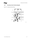
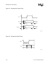
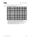
Figure 16-3, Figure 16-4, and Figure 16-5 show the typical timing for the BS register.
01112272831
JEDEC Code
Part Number
Version


