


2-2 SA-1100
Developer’s Manual
Functional Description
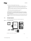
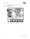
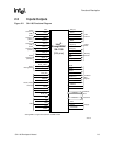
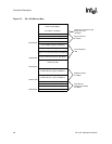
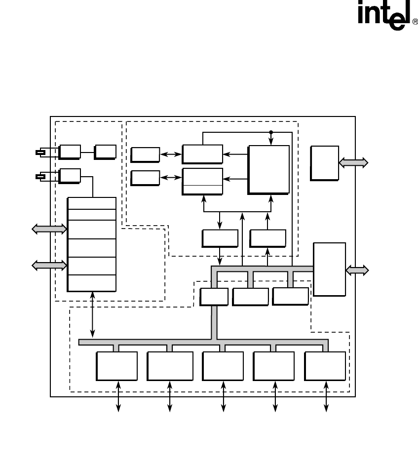
Figure 2-1 shows the functional blocks contained in the SA-1100 integrated processor. Figure 2-2
is a functional diagram of the SA-1100.
Figure 2-1. SA-1100 Block Diagram
A6832-01
Serial
Channel 0
UjSB
Serial
Channel 2
IrDA
Serial
Channel 3
UART
Serial
Channel 1
SDLC
JTAG
and
Misc
Test
Read
Buffer
Write
Buffer
Intel
®
StrongARM
®
*
SA-1100
IMMU
DMMU
32.768
KHz
3.686
MHz
OSC
OSC
PLL
Icache
(16 Kbytes)
Dcache
(8 Kbytes)
Peripheral Bus
System Bus
Load/Store Data
RTC
Minicache
PC
Instruction
Addr
ARM™*
SA-1
Core
OS Timer
General-
Purpose I/O
Interrupt
Controller
Power
Management
Reset
Controller
Serial
Channel 4
CODEC
* ARM is a trademark and StrongARM is a registered trademark of ARM Limited.
Processing
Core
System
Control
Module
(SCM)
Peripheral Control
Module (PCM)
DMA
Controller
LCD
Controller
Bridge
Memory
and
PCMCIA
Control
Module
(MPCM)