


SA-1100 Developer’s Manual 11-9
Peripheral Control Module
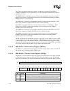
The value written to the device select DS<3:0> field specifies which DMA request this channel
responds to. The device datum width (DW) field value is fixed for each device type and indicates
whether the device’s data port is one or two bytes wide. If the datum width is programmed
incorrectly for a particular device select, then the results are unpredictable.
The device burst size (BS) field value is fixed for each device type. It indicates how many beats of
the datum width are transferred each time the device requests service. This value is chosen based
on the FIFO size of the particular device. If the burst size is programmed incorrectly for a particular
device select, then the results are unpredictable.
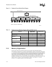
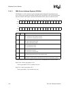
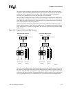
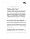
The device endianess E field value indicates the byte ordering within a word when data is read
from or written to memory. If the E bit is zero, then memory is assumed to be little endian. If the bit
is one, then memory is assumed to be big endian. The following figure shows big and little endian
DMA transfers.
Figure 11-2. Big and Little Endian DMA Transfers
The device transfer direction (RW) field indicates the direction of the transfer. A zero indicates that
the transfer is a write (with respect to the device) and that the flow of data will be from memory to
the device. If the RW field is programmed to a one, then the transfer is a read and the flow of data
will be from the device to memory. The transfer direction is fixed for each device type. If the burst
size is programmed incorrectly for a particular device select, then the results are unpredictable.
A6893-01
D<31>
Half-word wide
Device
Byte-wide
Device
D<0>
DMA
Controller
Big Endian DMA Transfers
3210
32
10
10
3
0
1
2
3
3
2
1
0
To FromFrom To
2
from memory
D<31>
Half-word wide
Device
Byte-wide
Device
D<0>
DMA
Controller
Little Endian DMA Transfers
3210
32
10
32
1
3
2
1
0
0
1
2
3
To FromFrom To
0
from memory