


SA-1100 Developer’s Manual 11-91
Peripheral Control Module
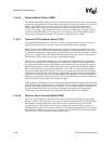
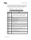
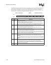
The following table shows the location of the bits within SDLC control register 1. RXE and TXE are
the only control bits in this register that are reset to a known state to ensure the SDLC is disabled
following a reset of the SA-1100. The reset state of all other control bits is unknown (indicated by
question marks) and must be initialized before enabling the SDLC. Note that SDCR1 may be written
while the SDLC is enabled to allow various modes to be changed during active operation.
Address: 0h 8002 0064 SDCR1 Read/Write
Bit 7 65 43210
RAE TUS AME TIE RIE RXE TXE AAF
Reset? ?? ??00?
Bit Name Description
0AAF
Abort after frame.
0 – Aborts not signalled following transmission of a frame. GPIO<17> controlled by system
unit.
1 – Abort is signalled after the end flag of a frame by transmitting 12 ones. GPIO<17> pin
forced high during idle; forced low during transmission of a frame or the abort.
Note: The user must configure GPIO<17> as an output within GPDR in the system
control
module.
1TXE
Transmit enable.
0 – SDLC transmit logic disabled. Control of the TXD1 pin is given to the PPC unit if SUS=0.
1 – SDLC transmit logic enabled if SUS=0.
2RXE
Receive enable.
0 – SDLC receive logic disabled. Control of the RXD1 pin is given to the PPC unit if SUS =0.
1 – SDLC receive logic enabled if SUS=0.
3RIE
Receive FIFO interrupt enable.
0 – Receive FIFO one- to two-thirds full or more condition does not generate an interrupt
(RFS bit ignored).
1 – Receive FIFO one- to two-thirds full or more condition generates an interrupt (state of
RFS sent to interrupt controller).
4 TIE
Transmit FIFO interrupt enable.
0 – Transmit FIFO half-full or less condition does not generate an interrupt (TFS bit ignored).
1 – Transmit FIFO half-full or less condition generates an interrupt (state of TFS sent to
interrupt controller).
5AME
Address match enable.
0 – Disable receiver address match function. Stores data from all incoming frames in
receive FIFO.
1 – Enable receiver address match function. Do not FIFO data unless address
recognized or incoming address contains all ones (0hFF).
6TUS
Transmit FIFO underrun select.
0 – Transmit FIFO underrun. Causes CRC and a flag to be transmitted, and masks
interrupt generation (TUR ignored).
1 – Transmit FIFO underrun. Causes an abort to be transmitted, and generates an
interrupt (state of TUR sent to interrupt controller).
7RAE
Receiver abort interrupt enable.
0 – Abort detected by the receiver. Does not generate an interrupt (RAS bit ignored).
1 – Abort detected by the receiver. Generates an interrupt (state of RAS sent to interrupt
controller).