9-4 SA-1100
Developer’s Manual
System Control Module
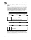
9.1.1.2 GPIO Pin Direction Register (GPDR)
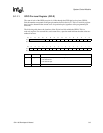
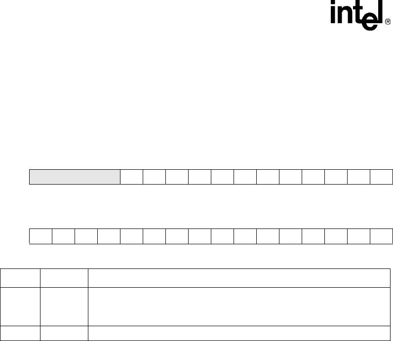
Pin direction is controlled by programming the GPIO pin direction register (GPDR). The GPDR
contains one direction control bit for each of the 28 port pins. If a direction bit is programmed to a
one, the port is an output. If it is programmed to a zero, it is an input. At hardware reset, all bits in
this register are cleared, configuring all GPIO pins as inputs. Soft resets and sleep reset have no
effect on this register. For reserved bits, writes are ignored and reads return zero. The following
table shows the location of each pin direction bit in the GPIO pin direction register.
Bit
31 30 29 28 27 26 25 24 23 22 21 20 19 18 17 16
R/W
Reserved PD27 PD26 PD25 PD24 PD23 PD22 PD21 PD20 PD19 PD18 PD17 PD16
Reset
0000000000000000
Bit
1514131211109876543210
R/W
PD15 PD14 PD13 PD12 PD11 PD10 PD9 PD8 PD7 PD6 PD5 PD4 PD3 PD2 PD1 PD0
Reset
0000000000000000
Bit Name Description
{n} PD{n}
GPIO port pin direction n (where n = 0 through 27).
0 – Pin configured as an input.
1 – Pin configured as an output.
31..28 — Reserved.


