


SA-1100 Developer’s Manual 9-11
System Control Module
9.2 Interrupt Controller
The SA-1100 interrupt controller provides masking capability for all interrupt sources and
combines them into their final state, either an FIQ or IRQ processor interrupt. The interrupt
hierarchy of the SA-1100 is a two-level structure.
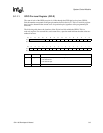
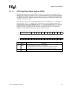
The first level of the structure, represented by the interrupt controller IRQ pending register (ICIP)
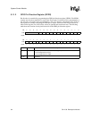
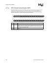
and the interrupt controller FIQ pending register (ICFP) contain the all-enabled and unmasked
interrupt sources. Interrupts are enabled at their source and unmasked in the interrupt controller
mask register (ICMR). The ICIP contains the interrupts that are programmed to generate an IRQ
interrupt. The ICFP contains all valid interrupts that are programmed to generate an FIQ interrupt.
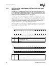
This routing is programmed via the interrupt controller level register (ICLR).
The second level of the interrupt structure is represented by registers contained in the source device
(the device generating the first-level interrupt bit). Second-level interrupt status gives additional
information about the interrupt and is used inside the interrupt service routine. In general, multiple
second-level interrupts are OR’ed to produce a first- level interrupt bit. The enabling of interrupts
is performed inside the source device.
In most cases, the root source of an interrupt can be determined through reading two register
locations: the ICIP or ICFP (depending on which interrupt handler the software is in) to determine
the interrupting device, followed by the status register within that device to find the exact function
needing service. When the SA-1100 is in idle mode (see the Section 9.5, “Power Manager” on
page 9-26), any enabled interrupt causes it to resume operation. The interrupt mask register is
ignored during idle mode. Figure 9-2 shows a block diagram of the interrupt controller.
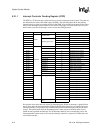
9.2.1 Interrupt Controller Register Definitions
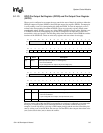
The interrupt controller contains four registers: the interrupt controller IRQ pending register
(ICIP), the interrupt controller FIQ pending register (ICFP), the interrupt controller mask register
(ICMR), and the interrupt controller level register (ICLR). Following reset, the FIQ and IRQ
interrupts are disabled within the CPU, and the states of all of the interrupt controller’s registers are
unknown and must be initialized by software before interrupts are enabled within the CPU.
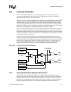
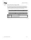
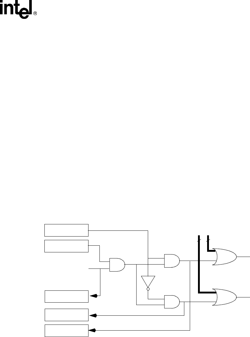
Figure 9-2. Interrupt Controller Block Diagram
Interrupt Mask
Register
Interrupt Source
Bit
Interrupt Level
Register
FIQ
Interrupt
IRQ
Interrupt
to
Processor
to
Processor
Interrupt Pending
Register
FIQ Interrupt
Pending Register
IRQ Interrupt
Pending Register
3131
All Other Qualified
Interrupt Bits