SA-1100 Developer’s Manual 11-193
Peripheral Control Module
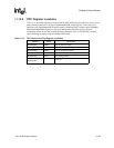
11.13.8 PPC Register Locations
Table 11-21 shows the registers associated with the PPC and the physical addresses used to access
them. Note that serial port 2 (ICP) has implemented HSSP control register 2 and serial port 4
(MCP) has also implemented MCP control register 1 within the PPC’s address space at 0h 9006
0028 and 0h 9006 0030 respectively. The user should ensure that these registers are not
accidentally written by any PPC routines that may attempt to write to all of the PPC’s address
space, including its reserved registers during initialization.
Table 11-21. PPC Control and Flag Register Locations
Address Name Description
0h 9006 0000 PPDR PPC pin direction register
0h 9006 0004 PPSR PPC pin state register
0h 9006 0008 PPAR PPC pin assignment register
0h 9006 000C PSDR PPC sleep mode direction register
0h 9006 0010 PPFR PPC pin flag register
0h 9006 0014 –
0h 9006 FFFF
— Reserved


