CPLD: Miscellaneous Registers
KAT4000 User’s Manual 10007175-02
7-6
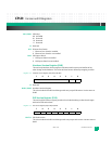
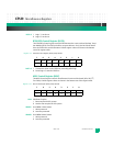
LDM: LED Debug Mode
Setting (0) puts the four debug LEDs into user mode allowing software to turn them off/on
individually. By default, they are in hardware debug mode and are connected to specific
internal/external signals.
1 Debug mode probes are enabled (default)
0 Debug mode probes are disabled
DBG3-0: Debug LEDs
1On
0Off
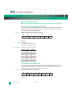
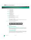
Jumper Settings Register (JSR)
The read-only Jumper Settings register indicates miscellaneous external settings. Default
register values are configuration dependent.
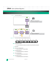
Register 7-7: Jumper Settings Register (JSR) at 0xfc40,0018
PRB: Logic Probe Input State
IROM: Ignore SROM
1SROM ignored
0 SROM not ignored
BFS: Boot From Socket
1 Boot from socketed flash (default)
0 Boot from NOR flash
R: Reserved
TID3-0: Transition Module ID
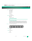
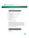
RTM GPIO State Register (RGSR)
The read-only RTM GPIO State register reads the state of the GPIO lines to/from the RTM.
Default register values are configuration dependent.
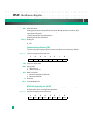
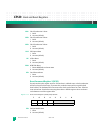
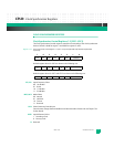
Register 7-8: RTM GPIO State Register (RGSR) at 0xfc40,0038
76543210
PRB IROM BFS R TID3 TID2 TID1 TID0
76543210
RIO7 RIO6 RIO5 RIO4 RIO3 RIO2 RIO1 RIO0


