Rear Transition Module: Setup
KAT4000 User’s Manual 10007175-02
13-6
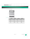
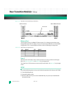
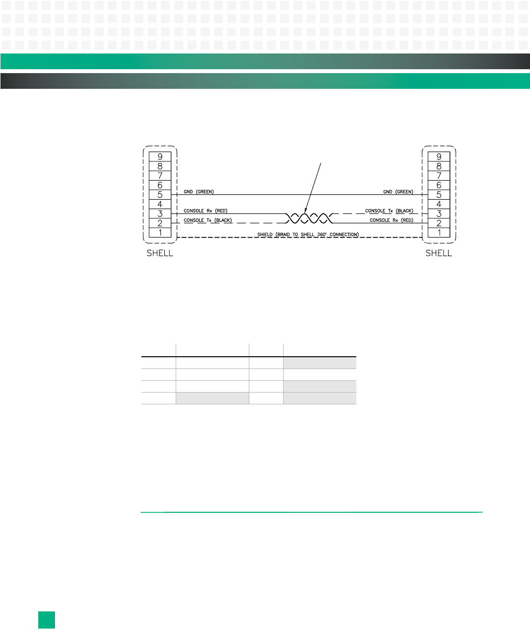
Figure 13-4: Standard Console Cable Wiring, #10007665-xx
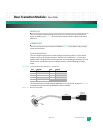
Ethernet Port
The face plate has one 10/100BASE-T Ethernet port, P3, for debug purposes that routes
through P30 to the GbE Core Switch. This port is not functional with the no-CPU KAT4000
configuration. This is a standard RJ45 connector, with the following pin assignments.
Table 13-3: Ethernet Port Pin Assignments, P3
Zone 3
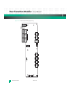
P30-P32 are the ATCA 80-pin Zone 3 (ZD) connectors for routing serial host and fat pipe
data. See
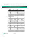
Table 12-4, Table 12-5 and Table 12-6 for pin assignments.
The 24-pin Zone 3 P33 connector routes serial I/O to the AMCs. See
Table 12-7 for pin assign-
ments.
SETUP
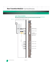
You need the following items to set up and check the operation of the Emerson KAT-Z3DB:
❐ The KAT4000 baseboard
❐ Compatible AMC modules
❐ Micro-D cable, Emerson part number C0007665-00 (cross-pinned) or C0007664-00
(straight-through)
Pin: Signal: Pin: Signal:
1 TX+ 5 no connect
2TX- 6RX-
3 RX+ 7
no connect
4
no connect 8 no connect
DB9 Connector Micro DB9 Connector


