


10007175-02 KAT4000 User’s Manual
A-1
Section A
Appendix A
NO-CPU KAT4000
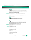
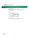
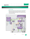
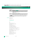
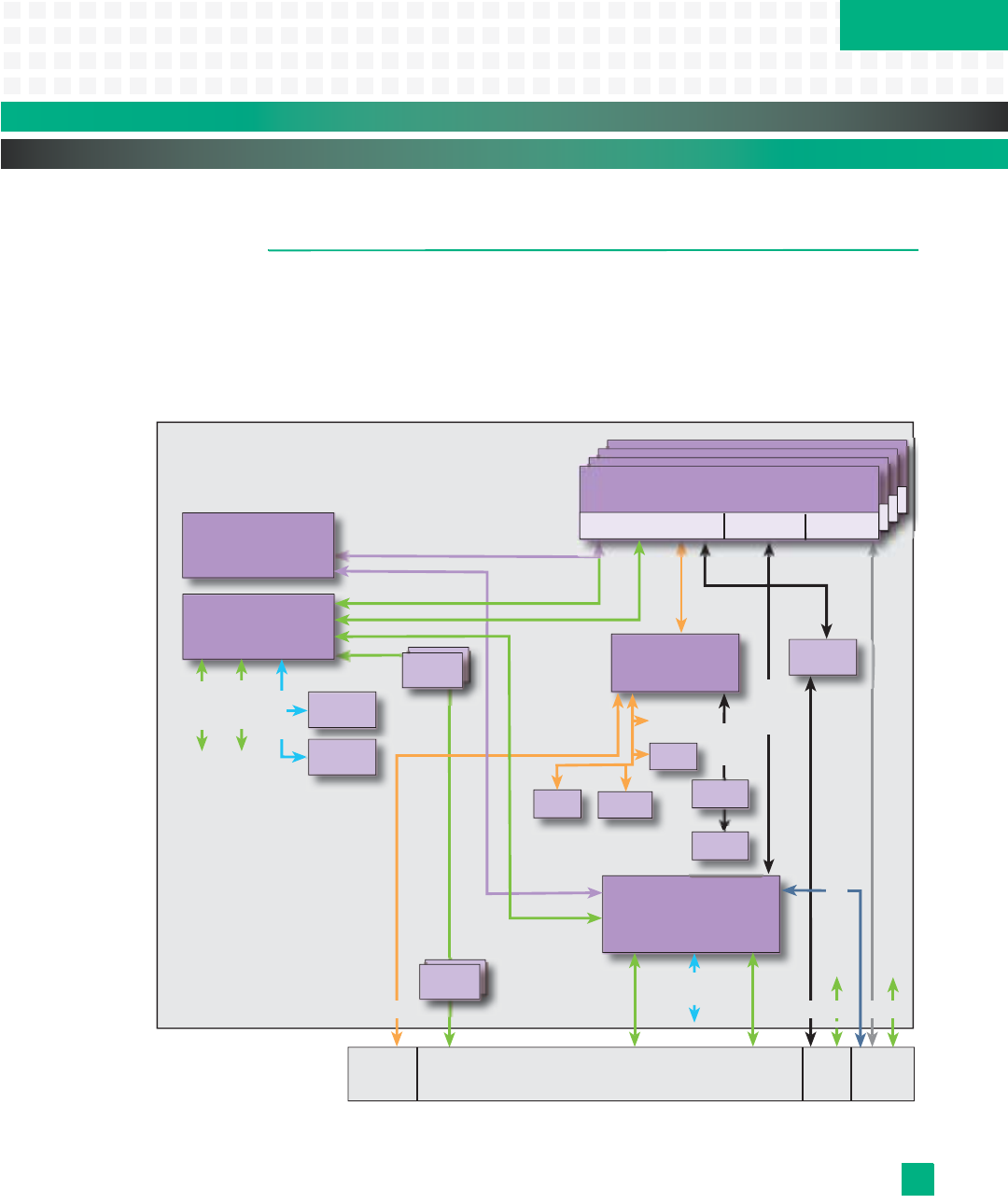
The following block diagram provides a functional overview for the no-CPU KAT4000 board
configuration. This configuration includes 256 Kb of SRAM memory used by the internal
8051 microcontroller on the VSC7376 Ethernet core switch for run time code storage. This
configuration omits SDRAM and NOR and NAND flash. Also, this configuration may not sup-
port some IPMC payload features.
Figure A-1: No-CPU KAT4000 System Block Diagram
IPMB Base High Speed
Fabric A
Clock RTM I/O
(Optional)
High Speed
Fabric B
Clock
IPMC
To
Core
Eth
Switch
(Opt.)
GbE
Xfmr
Xfmr (2)
GbE
PHYs (2)
Fat Pipe Switch Module
Sensors
-48V
Cnvrtr
AMC
A-to-D
EIA-232
Xcvr
Serial
Header
AMC (x4) Single-Width,
Half-/Full-/Extended-Height
PCIe or GbE
on port 1
To
Core
Eth
Switch
PEX8524
PCI Express Switch
(Optional)
VSC7376
Ethernet Core Switch
Layer 2 (Optional)
SERDES
4 SERDES
SERDES
2 SGMII
SERDES
4 SERDES
To Zone 3
To Update Channel
on J20 (Optional)
4 SERDES
Private I
2
C
Serial 2
4 SERDES
42
22
9
sRIO
(x4)
Switch
SRAM
To Zone 3
To
local
bus
PCIe
(x1 or x4)
IPMB-L I
2
C
Socketed
Flash
2 SERDES
Local bus
P10 J20 Zone 3J23