


Setup: KAT4000 Circuit Board
10007175-02 KAT4000 User’s Manual
2-9
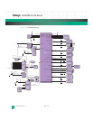
JTAG Interfaces
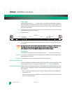
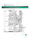
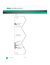
The KAT4000 provides the capability for JTAG type boundary scan testing. The IPMC con-
trols the two JTAG interfaces (hubs), see
Fig.2-6. One JTAG hub is connected to the fat pipe
switch module, two PLDs, and the four AMC sites. The other hub is connected to the Ether-
net core switch, the PCI Express switch, the processor, the GbE PHYs, and the synchroniza-
tion clock circuitry. See
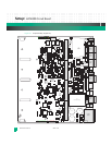
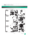
Fig. 2-4 and Fig. 2-5 for the location of individual headers.
Figure 2-6: JTAG Hubs
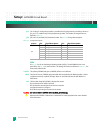
P1: The 16-pin JTAG/COP P1 header is provided for debug purposes for the processor. This inter-
face provides for boundary-scan testing and COP debugger support of the CPU (see
Fig.3-2)
and is compliant with the IEEE 1149.1 standard. The header pin assignments are defined in
Table 3-6.
C
aution: Install a shunt on JP1 pins 1:2 before using the JTAG/COP interface (P1) to enable CPU
J
TAG/COP access. Attempting to use the JTAG/COP interface without this shunt in place may
c
ause damage to the board. Refer to
Table 7-3 for JP1 pin details.
JP3: The 10-pin JTAG JP3 header is provided for programming In-System Programmable (ISP)
PLDs (see
Fig. 7-2). The header pin assignments are defined in Table 7-2.
AMC 1
AMC 2
AMC 4
AMC 3
VSC7376
Ethernet Core Switch
Layer 2
PEX8524
PCI Express Switch
MPC8548
Processor
COP/JTAG
P1
SCANSTA112
JTAG Multiplexer
SCANSCA112
JTAG
Multiplexer
Master
Port 1
Port 2
Port 3
Port 4
Port 5
Port 6
Port 0
SCANSTA112
JTAG Multiplexer
SCANSCA112
JTAG
Multiplexer
Master
Port 1
Port 2
Port 3
Port 4
Port 5
Port 6
Port 0
GbE PHY
(5)
Clock
Synch. (3)
KSL PLD
IPMC PLD
Prog.
Header JP3
IPMC GPIO
JTAG/Debug
Header J35
Fat Pipe
Switch Module
Config.
Header JP1
!