


Central Processing Unit: No Processor Configuration
10007175-02 KAT4000 User’s Manual
3-15
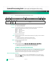
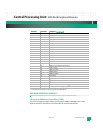
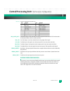
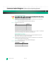
Table 3-6: Processor JTAG/COP Pin Assignments (P1)
CPU_CKSTP_OUT*: Checkstop Output—when asserted, this output signal indicates that the CPU has detected a
checkstop condition and has ceased operation.
CPU_TCK: Test Clock Input—scan data is latched at the rising edge of this signal.
CPU_TDI: Test Data Input—this signal acts as the input port for scan instructions and data.
CPU_TDO: Test Data Output—this signal acts as the output port for scan instructions and data.
CPU_TMS: Test Mode Select—this input signal is the test access port (TAP) controller mode signal.
DEBUG_HRESET*: Hard Reset—this input signal indicates that a complete Power-on Reset must be initiated by
the processor.
DEBUG_SRESET*: Soft Reset—this input signal indicates that the processor must initiate a System Reset inter-
rupt.
DEBUG_TRST*: Test Reset—this input signal resets the test access port.
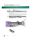
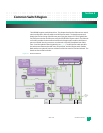
NO PROCESSOR CONFIGURATION
If a processor is not used on the KAT4000, the Ethernet core switch and GbE fat pipe switch
module (optional) are managed by an 8051 microcontroller internal to each switch. Cus-
tom configuration of the switch is possible through one of two user interfaces on each
switch. See “Appendix A” for more information.
Pin: Signal: Pin: Signal:
1CPU_TDO 2Not connected
3CPU_TDI 4DEBUG_TRST*
5
Not connected 6 JT_3_ 3V (fused)
7CPU_TCK 8
Not connected
9CPU_TMS 10
Not connected
11 DEBUG_SRESET* 12 GND
13 DEBUG_HRESET* 14
Not connected
15 CPU_CKSTP_OUT* 16 GND