Common Switch Region: PCI Express Switch (optional)
KAT4000 User’s Manual 10007175-02
4-8
PCI Express Interface
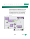
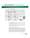
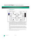
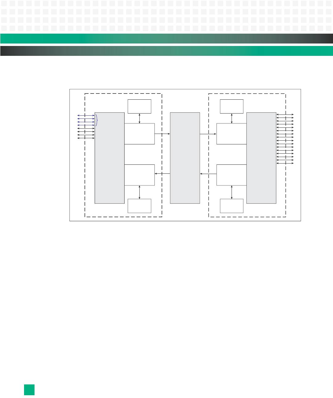
Figure 4-3: PEX 8524 Block Diagram
The stations implement the PCI Express Base 1.0a Physical, Data Link, and Transaction layers.
Each PCI Express station is able to support up to 16 integrated Serializer/De-serializer
1000Base-BX (SerDes) modules, which provide PCI Express hardware interface lanes. These
lanes can be configured to support up to four PCI Express ports per station. The PEX 8524
contains two stations (Station 0 and Station 1), connected by non-blocking Crossbar Switch
fabric.
From the system model viewpoint, each PCI Express port is a virtual PCI-to-PCI bridge
device and contains its own set of PCI Express Configuration registers. One of the ports on
either station can be designated the Upstream port (or primary bus in PCI terms). Through
use of the Upstream port, the firmware configures the other ports during standard PCI enu-
meration.
Note: The PCI Express Upstream Station supports Upstream ports and Downstream ports at the same time, but
lanes from different stations cannot be combined to form ports.


