


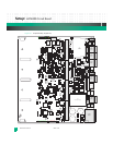
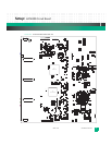


Setup: KAT4000 Circuit Board
KAT4000 User’s Manual 10007175-02
2-6
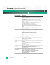
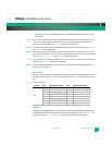
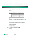
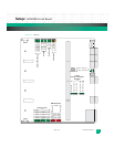
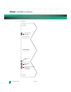
Table 2-3: Jumpers–JP2 and JP7
Note: Jumper settings for JP7 pins 1:2, 3:4 and 5:6 are not applicable to the no-CPU KAT4000 board configuration.
Jumper: Shunt Description:
Register
Map:
JP2
1:2 IPMC Mode bit MD2
out-factory use only–used for initial programming of the IPMC
controller (default)
N/A
3:4 IPMC Mode bit MD1
out-factory use only–used for initial programming of the IPMC
controller (default)
JP7
1:2 Boot from socket
in-boot from ROM socket (default)
out-boot from soldered flash
7-7
3:4 Ignore SROM
in-CPU ignores SROM (default)
out-CPU loads from SROM
5:6 Boot redirect (see Register Map 7-4 and Register Map 7-15)
in-disabled The board only attempts to boot from the device
specified by JP7 1:2.
out- enabled (default) The board cycles through the boot
devices until a valid boot image is executed.
7:8 Logic probe–Reserved
out-(default)
9:10 Standalone (SA) mode
in-in ATCA standalone mode, the IPMC disconnects IPMB-0, then
activates/deactivates the board itself
out-in ATCA normal mode, the IPMC communicates with the
shelf manager to activate/deactivate the board (default)