Setup: KAT4000 Circuit Board
KAT4000 User’s Manual 10007175-02
2-10
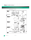
JP1: The 10-pin JP1 configuration header is provided for PLD programming. Installing a shunt on
JP1, pins 1:2, enables the JP3 PLD programming header. The header pin assignments are
defined in
Tab le 7- 3.
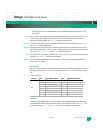
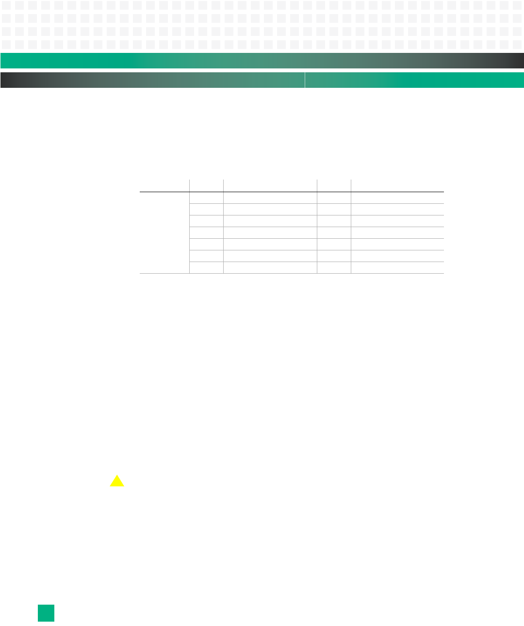
J35: J35 is the 14-pin IPMC JTAG/emulation header. See
Tab le 2 - 4 for signal descriptions.
Table 2-4: J35 Signal Descriptions
LEDs
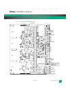
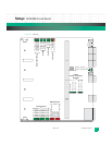
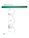
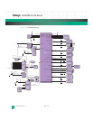
See Fig. 2-7 for the on-board Light-Emitting Diodes (LEDs). The KAT4000 has four front
panel LEDs. See
Fig. 2-8 for their location. The debug LED codes are defined in Table 14-1. The
front panel LEDs include:
2 and 3: The yellow (CR2000) and green (CR2002) LEDs are user defined.
OOS: The Out Of Service (CR2003) programmable LED controlled by the IPMI controller is either
red (North America) or yellow (Europe). When lit, this LED indicates the KAT4000 is in a
failed state.
HS: The blue Hot Swap LED (CR2001) displays four states:
On-the board can be safely extracted
Off-the board is operating and not safe for extraction
Long blink-insertion in progress
Short blink-requesting permission for extraction
Caution: Do not remove the KAT4000 while the blue LED is blinking.
Reference the PICMG® 3.0 Revision 2.0 AdvancedTCA™ Base Specification for more detailed
LED information.
Jumper: Pin: Signal Description: Pin: Signal Description:
J35
1IPMC_TCK 2GND
3IPMC_TRST* 4GND
5IPMC_TDO 6GND
7 IPMC_EMUL_RESI* 8 3_3 volts
9IPMC_TMS 10GND
11 IPMC_TDI 12 GND
13 IPMC_RES* 14 GND
!


