


10007175-02 KAT4000 User’s Manual
2-1
Section 2
Setup
This chapter describes the physical layout of the board and the setup process, including
power requirements and environmental considerations. This chapter also includes trouble-
shooting, service, and warranty information.
ELECTROSTATIC DISCHARGE
Before you begin the setup process, please remember that electrostatic discharge (ESD)
can easily damage the components on the KAT4000 hardware. Electronic devices, espe-
cially those with programmable parts, are susceptible to ESD, which can result in opera-
tional failure. Unless you ground yourself properly, static charges can accumulate in your
body and cause ESD damage when you touch the board.
Caution: Use proper static protection and handle KAT4000 boards only when absolutely necessary.
Always wear a wriststrap to ground your body before touching a board. Keep your body
grounded while handling the board. Hold the board by its edges–do not touch any
components or circuits. When the board is not in an enclosure, store it in a static-shielding
bag.
To ground yourself, wear a grounding wriststrap. Simply placing the board on top of a
static-shielding bag does not provide any protection–place it on a grounded dissipative
mat. Do not place the board on metal or other conductive surfaces.
KAT4000 CIRCUIT BOARD
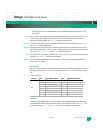
The KAT4000 is a 16-layer, 8U form factor circuit board that conforms to the PICMG 3.0
Rev. 2 and AMC.0 Rev. 2 mechanical specifications with the exception of a couple non-con-
formances. See the KAT4000 Errata for details. It has the following physical dimensions:
Table 2-1: Circuit Board Dimensions
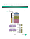
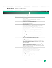
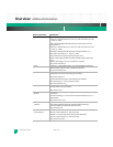
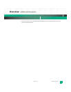
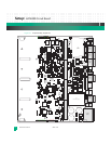
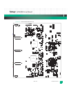
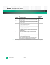
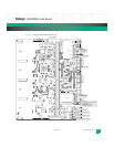
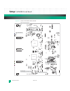
The following figures show the component maps for the KAT4000 circuit board. Figures are
also provided for the front panel, LEDs, fuse, jumper and JTAG locations.
Width: Depth: Thickness:
Component
Height (top side):
Component Height
(bottom side):
12.687 in.
(322.25 mm)
11.024 in.
(280.0 mm)
0.075 in.
(1.9 mm)
< 0.84 in.
(21.33 mm)
< 0.144 in.
(3.65 mm)
!