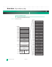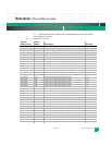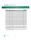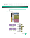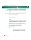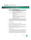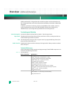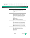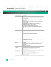
Overview: Physical Memory Map
KAT4000 User’s Manual 10007175-02
1-8
1. Depends on Flash/memory size.
2. Both the PCI Express Switch and sRIO Fat Pipe Switch Module are optional. If both devices are discovered onboard, then the PCIe
switch will be allocated 512 MB and the sRIO fat pipe switch module will be allocated 1 GB of addressable space. If neither device
is found onboard, the entire 1.5 GB area is reserved.
FC40,003C R/W RTM GPIO Control Register (RGCR) 7-7
FC40,0038 R RTM GPIO State Register (RGSR) 7-6
FC40,0034 R/W MISC Control (PCIe, SIO, I
2
C, Test Clock) Register (MISC) 7-7
FC40,0030 R Boot Device Redirection Register (BDRR) 7-12
FC40,002C R/W Scratch Register 1 (SCR1) 7-8
FC40,0028 W Reset Command Register 2 (RCR2) 7-10
FC40,0024 W Reset Command Register 1 (RCR1) 7-9
FC40,0020 R Reset Event Register (RER) 7-9
FC40,001C R/W LED Control Register (LEDR) 7-5
FC40,0018 R Jumper Settings Register (JSR) 7-6
FC00,0014 – Reserved –
FC40,0010 R Hardware Configuration Register 0 (HCR0) 7-4
FC40,000C R/W PLL Configuration Register (PLLC) 7-4
FC40,0008 R PLD Version Register (PVR) 7-3
FC40,0004 R Hardware Version Register (HVR) 7-3
FC40,0000 R Product ID Register (PIDR) 7-2
FC18,0000 – Reserved –
FC14,0000 R/W Fat Pipe Ethernet Switch Registers (if installed) (256 KB) 5-2
FC12,0000 – Reserved –
FC10,0000 R/W Ethernet Core Switch Registers (128 KB) 4-2
FC00,8000 – Reserved –
FC00,0000 R/W NAND Flash (32 KB) 6-2
E200,0000 – Reserved
1
–
E000,0000 R/W NOR Flash (32 MB) 6-1
A000,0000 R/W PCI Express Switch or sRIO Fat Pipe Switch Module (if installed)
(1 GB)
2
4-7 or 5-22
8000,0000 R/W PCI Express Switch (if installed) (512 MB)
2
4-7
4000,0000 – Reserved
1
–
0000,0000 R/W SDRAM DDR2 (512 MB/1 GB) 6-2
Physical
Address (hex):
Access
Mode: Description:
See Page:
(continued)


