Setup: KAT4000 Circuit Board
10007175-02 KAT4000 User’s Manual
2-5
• Zone 3 (ATCA) is for the optional Rear Transition Module (RTM) I/O interconnect—J30
through J33
P10: This connector provides the power and IPMB to the KAT4000. The P10 connector has four
levels of sequential mating to provide the proper functionality during live insertion or
extraction of the KAT4000. See
Table 12-1 for the pin assignments.
J20, J23: The 80-pin Zone 2 (ZD) connectors provide three levels of sequential mating. See
Tab le 1 2 -2
and
Table 12-3 for pin assignments.
J30-J32: The 80-pin Zone 3 (ZD) connectors provide an interconnect to an optional RTM. Connec-
tions include AMC ports 12-20, serial ports, a debug Ethernet port, and various other inter-
faces. See
Tab le 1 2 -4 , Table 12-5 and Table 12-6 for pin assignments.
J33: The 24-pin Zone 3 connector provides the 3.3 volt, 12 volt, and transmit/receive signals to
the AMCs. See
Table 12-7 for the pin assignments.
J2000: This hot swap switch header is a connector only–a switch assembly (P/N 10005468-xx)
connects to this socket.
Header JP4
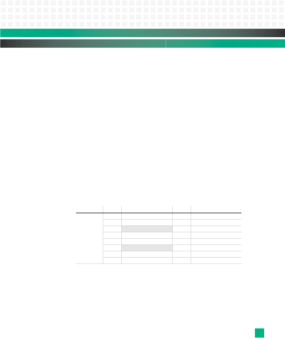
JP4 is the 16-pin serial port header for the IPMC debug console, fat pipe debug console, and
host debug console. See
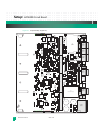
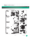
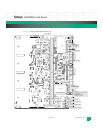
Tab le 2 - 2 for signal descriptions. See Fig. 2-4 for the header’s loca-
tion.
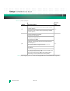
Table 2-2: JP4 Signal Descriptions
Jumpers
The following KAT4000 jumpers select the boot device, SROM initialization, logic probe,
and whether the IPMC will communicate with the shelf manager system. See
Tab le 2 - 3 for
jumper descriptions.
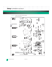
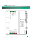
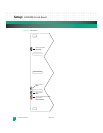
Fig.2-4 and Fig.2-5 show jumper, switch and fuse locations.
Jumper: Pin: Signal Description: Pin: Signal Description:
JP4
1 IPMC_RS232_TX 2 GND
3 IPMC_RS232_RX 4 GND
5
no connect 6 GND
7FP_CONN_RX 8GND
9 FP_CONN_TX 10 GND
11
no connect 12 GND
13 HOST_CONN_RX 14 GND
15 HOST_CONN_TX 16 GND


