Connectors: Zone 2
KAT4000 User’s Manual 10007175-02
12-2
ZONE 2
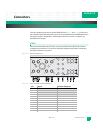
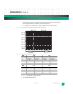
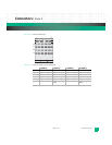
Zone 2 (ZD) defines five backplane connectors, J20 through J24, which support the data
transport interface. The KAT4000 is a Base node board supporting two Base channels,
therefore only the J23 connector is installed to support the 10BASE-T, and/or 100BASE-TX,
and/or 1000BASE-T Ethernet. Connector J20 is also used for the optional Update Channel
and synchronization clock interface. Each connector provides 40 differential signal contact
pairs, with each pair carrying an individual L-shaped ground contact. The ZD-style connec-
tor provides three levels of sequential mating, the third and shortest signal level is not used
with PICMG 3.0 backplanes. The Zone 2 connector array supports four different interfaces
to the ATCA backplane:
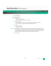
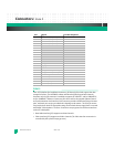
• Base Node Interface (J23) supports two Base channels
• Fabric Interface (J23) supports two Fabric channels (The fabric interface connection is
controlled by the system E-keying process)
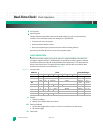
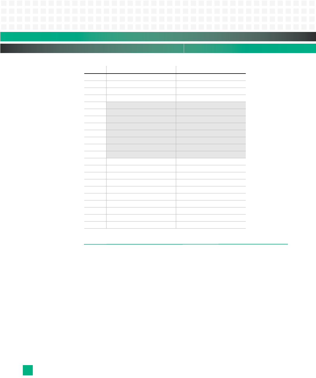
13 IPMBA Clock (SCL port A) third
14 IPMBA Data (SDA port A) third
15 IPMBB Clock (SCL port B) third
16 IPMBB Data (SDA port B) third
17
no connect third
18
no connect third
19
no connect third
20
no connect third
21
no connect third
22
no connect third
23
no connect third
24
no connect third
25 Shelf ground first
26 Logic ground first
27 Enable B fourth
28 Voltage Return A (-48RTNA) first
29 Voltage Return B (-48RTNB) first
30 -48 volt Early A first
31 -48 volt Early B first
32 Enable A fourth
33 -48 volt A (-48A) second
34 -48 volt B (-48B) third
Pin: Signal: Insertion Sequence:


